
Installation Sheet
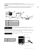
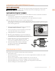
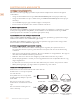
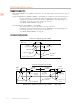
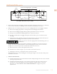
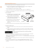
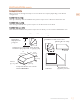
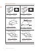
Table Of Contents
- SAFETY PRECAUTIONS - BEFORE YOU BEGIN
- MODEL NUMBERS
- RATING LABEL
- REGULATORY / CODE REQUIREMENTS
- USING THE VENTILATION SYSTEM
- Cleaning and Maintenance
- Troubleshooting
- DUCTING DO’S AND DON’TS
- Installation
- VENT ACCESSORIES
- PARTS / SERVICE
- LIMITED WARRANTY
- PRÉCAUTIONS DE SÉCURITÉ - AVANT DE COMMENCER
- NUMÉROS DE MODÈLE
- PLAQUE SIGNALÉTIQUE
- RESPECT DE LA RÉGLEMENTATION ET DES CODES EN VIGUEUR
- Mode d’emploi
- NETTOYAGE ET ENTRETIEN
- DÉPANNAGE
- BONNE PRATIQUE DE CANALISATION
- Installation
- Accessoires de ventilation
- Pièces / service
- GARANTIE LIMITÉE

INSTALLATION
TO REDUCE THE RISK OF FIRE, ELECTRIC SHOCK, OR INJURY TO
PERSONS, OBSERVE THE FOLLOWING:
a) Installation work and electrical wiring must be done by qualified person(s) in accordance with
all applicable codes and standards, including fire-rated construction.
b) Sufficient air is needed for proper combustion and exhausting of gases through the flue
(chimney) of fuel burning equipment to prevent back drafting. Follow the heating equipment
manufacturer’s guideline and safety standards such as those published by the National Fire
Protection Association (NFPA), and the American Society for Heating, Refrigeration, and Air
Conditioning Engineers (ASHRAE) and the local code authorities.
c) When cutting or drilling into wall or ceiling, do not damage electrical wiring and other hidden
utilities.
d) Ducted fans must always be vented to the outdoors.
TO REDUCE THE RISK OF FIRE, USE ONLY METAL DUCTWORK.
TO REDUCE THE RISK OF FIRE OR ELECTRICAL SHOCK, DO NOT USE THIS BLOWER WITH
ANY SOLID-STATE SPEED CONTROL DEVICE.
INSTALLATION DETAILS INSTALLATION DETAILS
1. Read all instructions thoroughly before beginning installation. Note: These instructions apply
to Hestan hood liners only.
• See “DUCTING DO’S AND DON’TS” on page10.
• Weight and size: For safe installation, at least two people should be present to lift and hold the
liner. For larger liners, it is advisable to have a third person present to assist.
• Back Venting: If venting out the wall behind the hood instead of venting through the ceiling,
see “BACK VENTING” on page15 for details.
2. When installing a Hestan hood liner, it is recommended that the
bottom edge of the liner be located no more than 30” above the
cooking surface for optimum performance.
3. Install the duct(s) from the outside of the house down to the
location of the exhaust outlet(s) on the top of the liner, allowing
room for the optional transitions, if used.
a) If back venting, the elbows should be installed so that the non-
crimped end(s) are on the inside of the collar(s) of the exhaust
outlet(s). If a transition is used, install the duct so it will engage
1” of the transition outlet.
b) Consult the connection diagrams (following) for further details
on exhaust outlet placement.
c) Use foil HVAC tape (not gray cloth duct tape) to seal all joints.
See “VENT ACCESSORIES” on page16 for available Hestan
vent accessories.
Make sure that once the liner is mounted,
the motor cooling vents are not obstructed.
Cabinet with
vent liner
30”
[76.2 cm]
12”
[30.5 cm]
12”
[30.5 cm]
22-1/2”
[57.2 cm]
36”
[91.4 cm]
©2020 Hestan Commercial Corporation
11
EN