User’s Manual TC1
1. PROJECT DESCRIPTION TC1 is a MFS 2.4GHz transmitter with 7 toggle switch inputs, 4 push-button inputs, a 4-step gray code trigger input and 2 analog-inputs. It can control any MFS 2.4GHz receiver using a 32DK packet. It transmits with an on-board PCB inverted-F antenna. It is powered by a 3.3V lithium-iron battery or optional Cable Control backup. TC1 also has an external docking station connection for local battery charging. Power is enabled by attaching the removable E-STOP cap.
Conformément à la réglementation d'Industrie Canada, le présent émetteur radio peut fonctionner avec une antenne d'un type et d'un gain maximal (ou inférieur) approuvé pour l'émetteur par Industrie Canada. Dans le but de réduire les risques de brouillage radioélectrique à l'intention des autres utilisateurs, il faut choisir le type d'antenne et son gain de sorte que la puissance isotrope rayonnée équivalente (p.i.r.e.
2. TECHNICAL SPECIFICATION -20o to +70o Celsius Temperature Range Supply Voltage Battery Supply BATTERY 3.3-5.0V Operating Current Startup (RFID reading) 150-200mA With LCD 53mA Without LCD 30mA Vcc 3.1V +Us 4.
3. FUNCTIONAL DESCRIPTION 3.1. Theory of Operation Theory of Operation: 1. Power On To power on the TC1, a sufficient supply voltage must be applied across the BATTERY terminals (3.35.0V). Solder Jumper J3 should be closed and a TG-N_ESTOP board should be connected via the ESTOP connector. A magnetic ESTOP cap must be sufficiently close to magnetic sensor on the TG-N_ESTOP board.
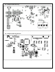
4. PCB 4.1.
4.2. Component Placement Top Figure 2: TX-TC1 Top Components 4.3.