User Guide SUMMARY This guide provides information about components, network connection, power management, security, backing up, and more.
© Copyright 2020 HP Development Company, L.P. AMD is a trademark of Advanced Micro Devices, Inc. USB Type-C and USB-C are registered trademarks of USB Implementers Forum. DisplayPort™ and the DisplayPort™ logo are trademarks owned by the Video Electronics Standards Association (VESA) in the United States and other countries. The information contained herein is subject to change without notice.
About this guide This guide provides basic information for using and upgrading this product. WARNING! Indicates a hazardous situation that, if not avoided, could result in serious injury or death. CAUTION: Indicates a hazardous situation that, if not avoided, could result in minor or moderate injury. IMPORTANT: Indicates information considered important but not hazard-related (for example, messages related to property damage).
iv About this guide
Table of contents 1 Computer features ........................................................................................................................................ 1 Product features .................................................................................................................................................... 1 Components ...........................................................................................................................................................
Wake-on LAN ....................................................................................................................................................... 33 Startup sequence ................................................................................................................................................. 34 Resetting the setup and power-on passwords ................................................................................................... 34 Power-on diagnostic tests .......
Standards and legislation .................................................................................................................................... 52 Standards .......................................................................................................................................... 52 Mandate 376 – EN 301 549 ............................................................................................ 52 Web Content Accessibility Guidelines (WCAG) .................................
viii
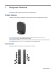
1 Computer features This chapter provides you with an overview of your thin client features. Product features To identify a typical computer configuration, read this section. Features vary depending on the model. For more information about the hardware and software installed on this thin client, go to http:// www.hp.com/go/quickspecs and search for this thin client. Various options are available for your thin client.
Table 1-1 Identifying the front panel components Front panel components 1 USB SuperSpeed ports (2) 8 Optional port.
WARNING! fire: To reduce the risk of personal injury or equipment damage from electric shock, hot surfaces, or Install the thin client in a location where children are unlikely to be present. Disconnect power from the thin client and allow the internal system components to cool before you touch them. Do not plug telecommunications or telephone connectors into the network interface controller (NIC) receptacles. Do not disable the AC power cord grounding plug.
To use the HP Quick Release: 1. Lay the thin client down with the right side up and the front side with the HP logo facing you. 2. Lift the side cover at the recess (1), and then remove the cover (2) from the thin client. NOTE: Retain the side cover for possible future use.
3. Set the thin spacer into the depression on the right side of the thin client. NOTE: Two spacers are included with the thin client. Use the thinner spacer when mounting the thin client. 4. Using four 10 mm screws included in the mounting device kit, attach one side of the HP Quick Release to the thin client as shown in the following illustration.
5. Using four screws included in the mounting device kit, attach the other side of the HP Quick Release to the device to which you will mount the thin client. Be sure that the release lever points upward. 6. Slide the side of the mounting device attached to the thin client (1) over the other side of the mounting device (2) on the device where you want to mount the thin client. An audible click indicates a secure connection.
On a wall: Under a desk: Setup 7
Into a dual VESA® mount: 1. 2.
3. 4. Supported orientation and placement The following illustrations demonstrate some of the supported orientation and placement options for the thin client. NOTE: You must adhere to the HP-supported orientation to ensure your thin clients function properly. Unless the thin client is mounted with the HP Quick Release, you must operate it with the stand attached to ensure proper airflow around the thin client.
● HP supports the vertical orientation for the thin client: ● You can place the thin client under a monitor stand with at least 2.54 cm (1 in) clearance: Unsupported placement HP does not support the following placements for the thin client: IMPORTANT: or both. Unsupported placement of thin clients could result in operation failure, damage to the devices, Thin clients require proper ventilation to maintain operating temperature. Do not block the vents.
● With a monitor on the thin client: Routine thin client care Use the following information to properly care for your thin client: ● Never operate the thin client with the outside panel removed. ● Keep the thin client away from excessive moisture, direct sunlight, and extreme heat and cold. For information about the recommended temperature and humidity ranges for the thin client, go to http://www.hp.com/go/quickspecs. ● Keep liquids away from the thin client and keyboard.
1. Remove or disengage any security devices that prohibit opening the thin client. 2. Remove all removable media, such as USB flash drives, from the thin client. 3. Turn off the thin client properly through the operating system, and then turn off any external devices. 4. Disconnect the AC power cord from the AC outlet and disconnect any external devices. 5. Tower orientation: Attach the stand to the bottom of the thin client. 6. 1.
Lay the thin client down with the right side up and locate the two screw holes in the grid on the right side of the thin client. Position the stand over the side of the thin client (1) and line up the captive screws in the stand with the screw holes in the thin client (2). Tighten the captive screws securely. 7. Reconnect the AC power cord and then turn the thin client on. NOTE: Be sure that at least 10.
2. Insert the security cable lock into the slot (1), and then use the key to lock it (2). NOTE: The security cable is designed to act as a deterrent, but it might not prevent the computer from being mishandled or stolen. Connecting the AC power cord Connect a power cable to your computer by following these steps. 1. Connect the power adapter to the thin client (1). 2. Connect the power cord to the power adapter (2). 3. Connect the power cord to an AC outlet (3).
Removing the access panel To remove the access panel, use these procedures. WARNING! Before removing the access panel, be sure that the thin client is turned off and the AC power cord is disconnected from the AC outlet. To remove the access panel: 1. Remove or disengage any security devices that prohibit opening the thin client. 2. Remove all removable media, such as USB flash drives, from the thin client. 3.
2. Loosen the captive screws to release the stand (1) and pull the stand off the thin client (2). Tower orientation Horizontal orientation 16 6. Lay the unit flat on a stable surface with the left side up. 7. Release the latch (1) on the right side of the rear I/O panel, rotate the I/O panel (2) to the left, and then lift it off the thin client.
8. Remove the screw that secures the access panel to the chassis (1). 9. Rotate the back up the access panel upward and lift it off the thin client (2). Replacing the access panel To replace the access panel, use these procedures. To replace the access panel: 1. Insert and rotate the access panel into place on top of the chassis (1), and then replace the screw (2).
2. Insert the hooks on the left side of the rear I/O panel (1) into the left side of the back of the chassis, rotate the right side (2) to the chassis, and then press it to the chassis until it locks in place. 3. Replace the thin client stand. 4. Reconnect the AC power cord and turn on the thin client. 5. Lock any security devices that were disengaged when the thin client access panel was removed.
To replace the M.2 storage module: 1. Remove the thin client access panel. See Removing the access panel on page 15. WARNING! To reduce risk of personal injury from hot surfaces, allow the internal system components to cool before you touch them. 2. Locate the M.2 socket on the system board. See Locating internal components on page 18. 3. Loosen the screw securing the storage module until the end of the module can be raised. 4. Pull the storage module out of the socket. 5.
6. Slide the new storage module into the M.2 socket on the system board and press the module connectors firmly into the socket. NOTE: A storage module can be installed in only one way. 7. Press the storage module down and use a screwdriver to tighten the screw and secure the module to the system board. 8. Replace the access panel. See Replacing the access panel on page 17. Removing and replacing the battery To remove and replace the battery, use these procedures.
3. To release the battery from its holder, squeeze the metal clamp that extends above one edge of the battery. When the battery pops up, lift it out (1). 4. To insert the new battery, slide one edge of the replacement battery under the holder’s lip with the positive side up. Push the other edge down until the clamp snaps over the other edge of the battery (2). 5. Replace the access panel. See Replacing the access panel on page 17.
A higher-speed DDR4 SODIMM module will actually operate at a maximum system memory speed of 2400 MHz. NOTE: The system does not operate properly when a unsupported memory module is installed. Installing a memory module To install a memory module, use these procedures. IMPORTANT: You must unplug the power cord and wait approximately 30 seconds for the power to drain before adding or removing the memory module.
4. Slide the new memory module (1) into the socket at approximately a 30° angle, and then press the memory module down (2) so that the latches lock it in place. NOTE: A memory module can be installed in only one way. Match the notch on the module with the tab on the memory socket. 5. Replace the access panel. See Replacing the access panel on page 17. The thin client automatically recognizes the new memory when you turn on the thin client.
2 Troubleshooting This chapter provides you with information to help troubleshooting your thin client. Computer Setup (F10) Utilities This information provides details of the Computer Setup Utility. Use Computer Setup (F10) Utility to do the following tasks: ● Change settings from the defaults or restore the settings to default values. ● Set the system date and time.
3. If you pressed esc, press f10 to enter Computer Setup. A choice of five headings appears in the Computer Setup Utilities menu: File, Storage, Security, Power, and Advanced. 4. Use the arrow (left and right) keys to select the appropriate heading. Use the arrow (up and down) keys to select the option that you want, and then press enter. To return to the Computer Setup Utilities menu, press esc. 5. To apply and save changes, select File, and then select Save Changes and Exit.
Table 2-1 Computer Setup—File (continued) Option Description Flash System BIOS Allows you to flash system BIOS or device firmware from a USB recovery key. Set Time and Date Allows you to set system time and date. Default Setup Allows you to: ● Save Current Settings as Default ● Restore Factory Settings as Default Apply Defaults and Exit Loads the original factory system configuration settings for use by a subsequent Apply Defaults and Exit action.
Computer Setup—Security This table provides information about the Computer Setup Security menu. NOTE: Support for specific Computer Setup options can vary, depending on the hardware configuration. Table 2-3 Computer Setup—Security Option Description Setup Password Allows you to set and enable a setup (administrator) password. NOTE: If the setup password is set, you must change Computer Setup options, flash the ROM, and make changes to certain plug and play settings under Windows.
Table 2-3 Computer Setup—Security (continued) Option Description System Security Provides these options: ● Data Execution Prevention (enable or disable)—Helps prevent operating system security breaches. Default is enabled. ● Virtualization Technology (enable or disable)—Controls the virtualization features of the processor. Changing this setting requires turning the computer off and then back on. Default is disabled. ● TPM Device—Lets you set the Trusted Platform Module (TPM) as available or hidden.
Table 2-5 Computer Setup—Advanced Option Heading Power-On Options Allows you to set: ● POST messages (enable or disable). Default is disabled. ● Press the esc key for Startup Menu (Displayed or Hidden). ● After Power Loss (off, on, or previous state). Default is Power off. Set this option as follows: – Power off causes the computer to remain off when power is restored. – Power on causes the computer to turn on automatically as soon as power is restored.
Changing BIOS Settings from the HP BIOS Configuration Utility (HPBCU) You can change some BIOS settings locally within the operating system without having to go through the F10 utility. This table identifies the items that you can control with this method. For more information about the HP BIOS Configuration Utility, see the HP BIOS Configuration Utility (BCU) User Guide at www.hp.com.
Table 2-6 Identifying the front panel components (continued) BIOS setting Default value Other values TPM Device Disable Enable TPM State Enable Disable Clear TPM Do not reset Reset Legacy Support Enable Disable (Note: The default value may be varied depends on the OS) Secure Boot Disable Enable (Note: The default value may be varied depends on the OS) Clear Secure Boot Keys Don’t Clear Clear Key Ownership HP Keys Custom Keys Fast Boot Disable Enable (Note: The default value may be
Table 2-6 Identifying the front panel components (continued) BIOS setting Default value Other values Num Lock State at Power- On Off On Internal Speaker Enable Disable PXE Option ROMs Enable Disable Updating or restoring a BIOS Use this information to update and restore BIOS. HP Device Manager HP Device Manager can be used to update the BIOS of a thin client. Customers can use a prebuilt BIOS or the standard BIOS upgrade package with an HP Device Manager File and Registry template.
Sometimes there are restrictions on which BIOS versions are allowed to be installed on a platform. If the BIOS that was on the system had restrictions, then you can use only the allowable BIOS versions for recovery. Diagnostics and troubleshooting LEDs To identify the troubleshooting LEDs, use this illustration and table. Table 2-7 Identifying the diagnostics and troubleshooting LEDs LED Status Power LED Off When the computer is plugged into the wall socket and the Power LED is off, the computer is off.
Startup sequence At startup, the flash boot block code initializes the hardware to a known state, and then performs basic power-on diagnostic tests to determine the integrity of the hardware. Initialization performs the following functions: 1. Initializes CPU and memory controller. 2. Initializes and configures all PCI devices. 3. Initializes video software. 4. Initializes the video to a known state. 5. Initializes USB devices to a known state. 6. Performs power-on diagnostics. 7.
Table 2-8 Startup diagnostic test (continued) Test Description Timer Tests timer interrupt by using polling method RTC CMOS battery Tests integrity of RTC CMOS battery NAND flash device Tests for proper NAND flash device ID present Interpreting POST diagnostic front panel lights and audible codes This section identifies the front panel light codes as well as the audible codes that can occur before or during POST that might not have an error code or text message associated with them.
Table 2-9 Interpreting POST diagnostic front panel lights and audible codes (continued) Activity Beeps Possible cause Recommended action Red power light flashes three times, and then the white power light flashes two times, once every second, followed by a 2 second pause. Beeps stop after fifth iteration but lights continue until problem is solved. 3.2 Prevideo memory error.
Table 2-10 Basic troubleshooting (continued) Issue Procedures The thin client does not turn on. 1. Verify that the power supply is good by installing it on a known working unit and testing it. If the power supply does not work on the test unit, replace the power supply. 2. If the unit does not work properly with the replaced power supply, have the unit serviced. 1. Verify that the network is operating and the network cable is working properly. 2.
No-disc (no-flash) computer troubleshooting This section is only for those computers that do not have ATA flash capability. Because there is no ATA flash in this model the boot priority sequence is: ● USB device ● PXE 1. When the computer boots, the monitor should display the following information: Table 2-11 No-disc (no-flash) computer troubleshooting Item Information Action MAC Address NIC portion of the system board is OK If there is no MAC Address, the system board is at fault.
Configuring a PXE server All PXE software is supported by authorized service providers on a warranty or service contract basis. NOTE: Customers with PXE issues and questions should contact their PXE provider for assistance. Additionally, see the following: – For Windows Server 2008 R2: http://technet.microsoft.com/en-us/library/7d837d88-6d8e-420cb68fa5b4baeb5248.aspx – For Windows Server 2012: http://technet.microsoft.com/en-us/library/jj648426.
NOTE: Optionally, you can use the tool on a Windows computer. This restore method will not work with all USB flash devices. USB flash devices that do not show up as removable drive in Windows do not support this restore method. USB flash devices with multiple partitions generally do not support this restore method. The range of USB flash devices available on the market is constantly changing. Not all USB flash devices have been tested with the HP Thin Client Imaging Tool.
7. Locate the (blue or green) two pin password jumper on header E49 (labeled PSWD) and remove it. 8. Remove AC power, wait 10 seconds until the computer's AC power has drained out, and press the Clear CMOS button. (This is usually a yellow push button labeled CMOS). 9. Replace the hood and AC power cord and turn the computer on. The passwords are now cleared, and all other user-configurable, nonvolatile memory settings are reset to their factory default values. 10. Open the F10 setup utility. 11.
3 Using HP PC Hardware Diagnostics You can use the HP PC Hardware Diagnostics utility to determine whether your computer hardware is running properly. The three versions are HP PC Hardware Diagnostics Windows, HP PC Hardware Diagnostics UEFI (Unified Extensible Firmware Interface), and (for select products only) Remote HP PC Hardware Diagnostics UEFI, a firmware feature.
4 Power cord set requirements The power supplies on some computers have external power switches. The voltage select switch feature on the computer permits it to operate from any line voltage of 100 V ac–120 V ac or 220 V ac–240 V ac. Power supplies on those computers that do not have external power switches are equipped with internal switches that sense the incoming voltage and automatically switch to the proper voltage.
Table 4-1 Power cord country-specific requirements (continued) 44 Country Accrediting Agency Country Accrediting Agency Canada (2) CSA Sweden (1) SEMKO Denmark (1) DEMKO Switzerland (1) SEV Finland (1) SETI United Kingdom (1) BSI France (1) UTE United States (2) UL Germany (1) VDE 1. The flexible cord must be Type HO5VV-F, 3-conductor, 0.75mm2 conductor size.
5 Computer operating guidelines, routine care, and shipping preparation Follow these guidelines to ensure the best performance and useful life of your computer. Operating guidelines and routine care HP has developed guidelines to help you properly set up and care for the computer and monitor. ● Keep the computer away from excessive moisture, direct sunlight, and extreme heat and cold. ● Operate the computer on a sturdy, level surface. Leave a 10.
1. Wear disposable gloves made of latex (or nitrile gloves, if you are latex-sensitive) when cleaning the surfaces. 2. Turn off your device and unplug the power cord and other connected external devices. Remove any installed batteries from items such as wireless keyboards. CAUTION: To prevent electric shock or damage to components, never clean a product while it is turned on or plugged in. 3. Moisten a microfiber cloth with water. The cloth should be moist, but not dripping wet. IMPORTANT: 4.
4. Wipe the exterior of the product gently with the moistened cloth. IMPORTANT: Keep liquids away from the product. Avoid getting moisture in any openings. If liquid makes its way inside your HP product, it can cause damage to the product. Do not spray liquids directly on the product. Do not use aerosol sprays, solvents, abrasives, or cleaners containing hydrogen peroxide or bleach that might damage the finish. 5. Start with the display (if applicable).
6 Specifications This section provides specifications for your thin client. For the latest specifications or additional specifications on the thin client, go to http://www.hp.com/go/ quickspecs/ and search for your specific thin client to find the QuickSpecs. Table 6-1 Specifications Metric U.S. Height 35 mm 1.38 in Width 200 mm 7.87 in Depth 200 mm 7.87 in Height 152 mm 5.98 in Width 200 mm 7.87 in Depth 208 mm 8.18 in Weight (without stand) 916 g 2.
7 Electrostatic discharge Electrostatic discharge is the release of static electricity when two objects come into contact—for example, the shock you receive when you walk across the carpet and touch a metal door knob. A discharge of static electricity from fingers or other electrostatic conductors may damage electronic components.
8 Accessibility HP's goal is to design, produce, and market products, services, and information that everyone everywhere can use, either on a stand-alone basis or with appropriate third-party assistive technology (AT) devices or applications. HP and accessibility Because HP works to weave diversity, inclusion, and work/life into the fabric of the company, it is reflected in everything HP does.
International Association of Accessibility Professionals (IAAP) IAAP is a not-for-profit association focused on advancing the accessibility profession through networking, education, and certification. The objective is to help accessibility professionals develop and advance their careers and to better enable organizations to integrate accessibility into their products and infrastructure. As a founding member, HP joined to participate with other organizations to advance the field of accessibility.
If you need additional support with the accessibility features on your HP product, see Contacting support on page 54.
● Understandable (by addressing readability, predictability, and input assistance) ● Robust (for instance, by addressing compatibility with assistive technologies) Legislation and regulations Accessibility of IT and information has become an area of increasing legislative importance. These links provide information about key legislation, regulations, and standards.
Other disability resources Many resources, including these examples, provide information about disabilities and age-related limitations. ● ADA (Americans with Disabilities Act) Technical Assistance Program ● ILO Global Business and Disability network ● EnableMart ● European Disability Forum ● Job Accommodation Network ● Microsoft Enable HP links These HP-specific links provide information that relates to disabilities and age-related limitations.
Index A accessibility 50, 53 accessibility needs assessment 51 Advanced menu, Computer Setup 28 assistive technology (AT) finding 51 purpose 50 AT (assistive technology) finding 51 purpose 50 audible codes 35 B beep codes 35 blinking lights 35 C caring for your computer 45 changing BIOS Settings 30 cleaning your computer 45 disinfecting 46 removing dirt and debris 45 components 1 computer operating guidelines 45 Computer Setup Advanced menu 28 File menu 25 Power menu 28 Security menu 27 Storage menu 26 Comp