
User's Manual


Aruba AP-120 Series Indoor Access Point | Installation Guide 7
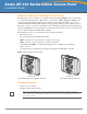
Ethernet Ports
The RJ45 Ethernet ports (ENET0 and ENET1) support 100/1000Base-T auto-sensing MDI/MDX
connections. Use these ports to connect the AP to a twisted pair Ethernet LAN segment or directly to an
Aruba Mobility Controller. Use a 4- or 8-conductor, Category 5 UTP cable up to 100 m (325 feet) long.
The 100/1000 Mbps Ethernet ports are on the bottom of the AP. These ports have RJ-45 female
connectors with the pin-outs shown in Table 1.
Serial Console Port
The serial console port allows you to connect the AP to a serial terminal or a laptop for direct local
management. This port is an RJ-45 female connector with the pinouts described in Table 2. Connect this
port in one of the following ways:
z Connect it directly to a terminal or terminal server using an Ethernet cable.
z Use a modular adapter to convert the RJ-45 (female) connector on the AP to a DB-9 (male)
connector, and connect the adapter to a laptop using an RS-232 cable. See Figure 7 for connector
details of the adapter.
NOTE
Aruba 12x APs are intended only for installation in Environment A as defined in IEEE 802.3.af, Power
over Ethernet. All interconnected equipment must be contained within the same building, including
the interconnected equipment’s associated LAN connections.
NOTE
When installed in an air-handling space, such as above suspended ceiling (plenum), the unit is
required to be powered through PoE only. Additional cabling such as Fast Ethernet (FE) cables
installed in such spaces should be suitable under NEC Article 800.50 and marked accordingly for
use in plenums and air-handling spaces with regard to smoke propagation, such as CL2-P, CL3-P,
MPP or CMP.
Table 1 Connector for Ethernet Ports ENET0 and ENET1
Connector Pin
Signal
Name
GE Connection
FE
Connection
PoE
1 BI_DA+ Bi-directional pair A+ RX+ POE negative
2 BI_DA– Bi-directional pair A– RX– POE negative
3 BI_DB+ Bi-directional pair B+ TX+ POE positive
4 BI_DC+ Bi-directional pair C+ Spare pair POE positive
5 BI_DC– Bi-directional pair C– Spare pair POE positive
6 BI_DB– Bi-directional pair B– TX– POE positive
7 BI_DD+ Bi-directional pair D+ Spare pair POE negative
8 BI_DB– Bi-directional pair D– Spare pair POE negative
Table 2 Connector for Serial Console Port
Connector Pin Signal Name Function
3TXD Transmit
4GND Ground
5GND Ground
6RXD Receive
Pins not listed are not connected.
1
2
3
4
5
6
7
8
1
2
3
4
5
6
7
8