
Installation Guide

8 Aruba AP-120 Series Indoor Access Point | Installation Guide
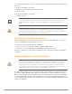
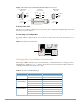
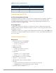
Figure 7 RJ-45 (Female) to DB-9 (Male) Modular Adapter Conversion
Power Connection
The AP-120 series AP has a single 5V DC power jack socket to support powering through an AC-to-DC
mains electric power adapter.
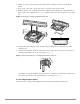
Connecting a Security Cable
To provide added security for the AP, you can attach a security cable to the back of the unit (see Figure
8).
Figure 8 Security Lock Connection
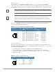
Verifying Post-Installation Connectivity
The integrated LEDs on the AP can be used at this point to verify that the AP is receiving power and
initializing successfully (see Table 3). Refer to the ArubaOS Quick Start Guide for further details on
verifying post-installation network connectivity.
Table 3 AP-120 Series LED Meanings
LED Color/State Meaning
PWR Green Steady Power on, device ready
Green flashing System initializing
ENET 0
(100/1000 Mbps)
Green/Amber off No link
Green on 1000 Mbps link
Amber on 10/100 Mbps link
Green/amber blinking Data activity
ENET 1
(100/1000 Mbps)
Green/Amber off No Link
Green on 1000 Mbps link
Amber on 10/100 Mbps link
Green/amber blinking Data activity
3
4
5
2
5
63
RJ-45 DB-9
Internal
Connections
TxD
GND
RxD
1
2
3
4
5
6
7
8
TxD
GND
RxD
RJ-45 Female
Pin-Out
Direction
Input
Output
DB-9 Male
Pin-Out
TxD
RxD
Ground
5
4
3
2
1
9
8
7
6
Direction
Input
Output