Aruba AP-175 Outdoor Access Point Installation Guide The Aruba AP-175 is a resilient, environmentally hardened, outdoor rated, dual-radio, dual-band IEEE 802.11 a/b/g/n wireless access point. This outdoor access point is part of Aruba’s comprehensive wireless network solution. The AP-175 works only in conjunction with an Aruba controller and each AP can be centrally managed, configured, and upgraded through the controller. The AP-175 requires ArubaOS 5.0.2.1 or later.
Package Contents AP-175 Access Point AP-175 Mounting Bracket Solar Shield Pole Anchors x 2 M4 x 16 bolts, flat washers, and spring washers x4 (These bolts are attached to the solar shield) M6 x 30 bolts, flat washers, and spring washers x2 M4 x 12 bolt, external-tooth washer, and OT copper lug x1 M8 x 110 bolt, flat washers, spring washers, and nuts x4 Metal Weatherproof Caps x2 for use on unused antenna interfaces RJ-45 Connector Kit with plastic RJ-45 connector (AP-1
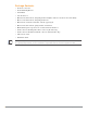
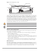
AP-175 Hardware Overview The following section describes the hardware features of the AP-175. Figure 1 AP-175 Overview (AP-175P shown) 5 6 4 3 7 2 8 1 1 Antenna Interface (Radio 1) 5 Antenna Interface (Radio 0) 2 USB Console Interface 6 Antenna Interface (Radio 1) 3 Reserved (AP-175P) or Power Interface (AP-175AC and AP-175DC) 7 Ethernet Interface (PoE) 4 Antenna Interface (Radio 0) 8 Grounding Point Antenna Interface The AP-175 requires the use of detachable outdoor-rated antennas.
USB Console Interface A USB serial console port is provided for connection to a terminal, allowing direct local management. Use the included USB console cable to connect to the AP. You can download the necessary driver for USBUART adapter from support.arubanetworks.com under the Tools & Resources tab.
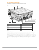
Figure 2 LED Layout RSSI for Radio 0 RSSI for Radio 1 P/S POE ETH Table 2 lists the meanings of the LEDs on the AP-175P outdoor access point.
AP-175AC/DC LED Status Indicators The AP-175 include visual indicators for power, link, heat and radio status. Additionally, each radio has a four-LED array that indicates received signal strength (RSSI). The RSSI LED indicators represent varying degrees in the RSSI level. The absence of a signal is indicated by no LED response, and full signal strength is indicated when all four LEDs are active and lit.
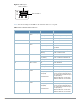
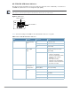
Table 3 AP-175AC/DC LED Status Indicators (Continued) LED Function Indicator Status R0 Radio 0 Status Off Radio 0 disabled On (Amber) Radio 0 enabled in WLAN mode Blinking Air Monitor (AM) mode Off Radio 1disabled On (Blue) Radio 1 enabled in WLAN mode Blinking Air Monitor (AM) mode Off RSSI disabled/no signal 4 Step Progressive Bars (Red) Each bar represents a progressive increase in signal strength, with 4 bars representing maximum signal strength (100%).
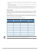
Identifying Known RF Absorbers/Reflectors/Interferences Sources Identifying known RF absorbers/reflectors/interference sources while out in the field during the installation phase is critical. Even though outdoor environments consist of fewer RF absorbers/reflectors/interference sources compared to indoor environments, ensure that these sources are identified and taken into consideration when installing and mounting an AP to its fixed outdoor location.
Be sure there is enough clearance from buildings and that no building construction may eventually block the path. For very long distance links, the curvature of the earth (20 cm per km) may need to be considered in the calculation of relative heights.
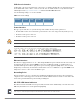
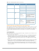
Figure 5 Antenna Height and Line of Sight Radio Line of Sight Visual Line of Sight 3 miles (4.8 km) 2.4 m A B 4.7 m 1.4 m 9m 20 m 17.7 m 12 m A wireless bridge or mesh link is deployed to connect building A to building B, which is located three miles (4.8 km) away. Mid-way between the two buildings is a small tree-covered hill. From the above table it can be seen that for a three-mile link, the object clearance required at the mid-point is 4.7 m (15.4 ft).
If radio interference is still a problem with your wireless bridge or mesh link, changing the antenna direction may improve the situation. Weather Conditions When planning wireless bridge or mesh links, you must take into account any extreme weather conditions that are known to affect your location. Consider these factors: ! Temperature: The wireless bridge or mesh link is tested for normal operation in temperatures from -30ºC to 55ºC.
Installing Antennas 1. Before connecting the antennas, identify which of your antennas are 2.4 GHz and which are 5 GHz. On the AP-175, the 2.4 GHz antennas must be installed the R1 radio interfaces and the 5.0 GHz must be installed on the R0 radio interfaces. 2. After identifying which antennas will go where, install them by placing the antenna connector over the corresponding connector and the AP and turning the connector clockwise until hand tight. Repeat this process for each antenna. 3.
Figure 6 Directly Connected Antennas AP175_11 Weep holes Figure 7 Cable Connections Connectors on bottom of antenna N-type connector on an RF cable AP175_16 N-type connector on a pigtail Aruba AP-175 Outdoor Access Point | Installation Guide 13
Important Points to Remember Do not cover the weep holes on the antennas. Doing so can restrict the release of condensation from the antennas. Proper weatherproofing is not a fast process. Set aside ample time to complete the steps outlined below. When wrapping, make the each layer of tape as flat as possible. Wrinkles and folds in the tape create places for water and moisture to gather. Weatherproofing Directly Connected Antennas First Wrapping of Tape 1.
Wrapping of Butyl Rubber 1. Cut a 3/4” (19 mm) strip of butyl rubber. 2. Wrap the strip of rubber around the taped connector (Figure 9) 3. Join the two ends by pushing them together until there is no longer a seam (Figure 10).
Second Wrapping of Tape 1. Cut a 4” (100 mm) strip of electrical tape from the roll. 2. Where you begin wrapping depends on the orientation of the antenna. Water should flow in the opposite direction of the wrapping to prevent water from entering the connector between the layers of tape. Therefore, if the antenna is facing up, you should begin wrapping at the AP end of the connector. This will ensure that your fourth and final layer will be layered correctly.
Weatherproofing Cable Connections First Wrapping of Tape 1. Prepare the antenna connector by cleaning and drying it. 2. Cut a 4” (100 mm) strip of electrical tape from the roll. Pre-cutting the tape into strips makes in easier to maneuver the tape around the connectors and other components but is not required. 3. Beginning at the top of the connector, tightly wrap the connection with a layer of the 3/4” (19mm) electrical tape. Overlap the tape to a half-width. 4.
Wrapping of Butyl Rubber 1. Cut a piece of butyl rubber large enough to wrap around the connector and extended past the first layer of tape. 2. Wrap the strip of rubber around the taped connector (Figure 13) 3. Join the two ends by pushing them together until there is no longer a seam (Figure 14).
Second Wrapping of Tape 1. Cut a 4” (100 mm) strip of electrical tape from the roll. 2. Using 3/4” (19mm) electrical tape, begin wrapping at the connector and create four layers. 3. After completing the fourth layer of tape, check your work to ensure there are no places where water can collect. If there are, you must smooth out those areas with additional layers of tape or remove the weatherproofing and begin again.
according to the network planning and technical requirements of communications equipment, as well as the considerations such as climate, hydrology, geology, earthquake, electric power, and transportation. Installing the AP-175 on a Pole 1. Attach the AP-175 on the mounting bracket using the two M6 x30 bolts (with flat and spring washers) on each side of the mounting bracket. AP175_03 Figure 16 Attaching the mounting bracket to the AP 2.
Figure 17 Attaching the mounting bracket to the pole Installing the AP-175 on a Wall 1. Begin by marking the screw points on the wall in the location you have selected. a. Put the mounting bracket on the installation position against the wall. b. Mark four expansion screw holes on the wall.
Figure 18 Position of the screw holes 2. Use a drill to create four holes on the four markings you created in the previous step. 3. Install wall (masonry) anchors. a. Insert a masonry anchor into each drilled hole. b. Tap the flat end of the anchor with a rubber hammer until the anchor is flush with the wall surface. 4. Attach the mounting bracket to the wall. a. Align the four holes in the mounting bracket with the anchors and insert four expansion screws through the installation holes into the anchors.
Figure 19 Attaching the AP to the Mounting Bracket Front Front Grounding the AP-175 The grounding must be completed before powering up the AP-175. The resistance of grounding wire should be less than 5 ohm and the grounding cable’s cross-section area should be no less than 6 mm.The grounding hole is at the right side of the AP-175. AP175_08 Figure 20 Grounding the AP-175 1.
Connecting the Ethernet Cable (AP-175P) To ensure that your outdoor access point (AP) maintains Ethernet connectivity and Power over Ethernet (PoE), you must use the included weatherproof connector kit and install it using the steps below. Failure to use the included weatherproof connector kit can lead to connectivity and PoE issues. Figure 21 Waterproof Ethernet Connector Cover 1 Shielded RJ45 connector 4 Locknut 2 Gasket Mat 5 Seal Ring 3 Waterproof Connector Socket 6 Sealing Nut 1.
Connecting the Ethernet Cable (AP-175AC/DC) To ensure that your outdoor access point (AP) maintains Ethernet connectivity and Power over Ethernet (PoE), you must use the included weatherproof connector kit and install it using the steps below. Failure to use the included weatherproof connector kit can lead to connectivity and PoE issues.
Figure 23 Connecting the Ethernet cable Connecting the Power Cable (AP-175 AC) ! Installation and service of Aruba products should be performed by Professional Installers in a manner that is consistent with the electrical code in force in the jurisdiction of deployment. In many countries this will require a licensed electrician to perform this operation. In Japan, this is a Certified Electrician by Ministry of Economy, Trade, and Industry.
Connecting the Power Cable (AP-175DC) ! Installation and service of Aruba products should be performed by Professional Installers. The AP-175DC requires an outdoor rated power cable to connect to a compatible DC power source. The AP-175 does not ship with any power cables; these are available as accessories and should be ordered separately. In addition to completed power cables, Aruba also offers an outdoor rated AC and DC connector kit that can be used to connect a compatible power cable to the AP-175.
Product Specifications Mechanical Dimensions (H x W x D) 10.2 inches x 9.4 inches x 4.1 inches 26 cm x 24 cm x 10.5 cm Weight: 7 lbs/3.25 kg Shipping Dimensions (H x W x D) 12.9 inches x 12.6 inches x 11.8 inches 33 cm x 32 cm x 30 cm Shipping Weight: 16.6 lbs/7.
4 x N-Type female antenna interfaces Other: 1 x USB console interface Wireless LAN AP type: Dual-radio, dual-band 802.11n outdoor Supported frequency bands (country-specific restrictions apply): 2.400 to 2.4835 GHz 5.150 to 5.250 GHz 5.250 to 5.350 GHz 5.470 to 5.725 GHz 5.725 to 5.850 GHz Available channels: Controller-managed, dependent upon configured regulatory domain Supported radio technologies: 802.11b: Direct-sequence spread-spectrum (DSSS) 802.
Safety and Regulatory Compliance Aruba Networks provides a multi-language document that contains country-specific restrictions and additional safety and regulatory information for all Aruba access points. This document can be viewed or downloaded from the following location: www.arubanetworks.com/safety_addendum ! RF Radiation Exposure Statement: This equipment complies with FCC RF radiation exposure limits. This equipment should be installed and operated with a minimum distance of 13.
European Union RoHS Aruba products also comply with the EU Restriction of Hazardous Substances Directive 2002/95/EC (RoHS). EU RoHS restricts the use of specific hazardous materials in the manufacture of electrical and electronic equipment. Specifically, restricted materials under the RoHS Directive are Lead (including Solder used in printed circuit assemblies), Cadmium, Mercury, Hexavalent Chromium, and Bromine.
High power radars are allocated as primary users of the 5.25 to 5.35 GHz and 5.47 to 5.6 GHz and 5.65 to 5.725 GHz bands. These radar stations can cause interference with and/or damage this device. Les radars haute puissance utilisent de façon prioritaire les bandes 5,25 - 5,35 GHz, 5,47 - 5,6 GHz et 5,65 5,725 GHz. Par conséquent, ces radars peuvent provoquer des interférences avec ce périphérique et endommager ce dernier. This device will not operate on channels which overlap the 5600 - 5650 MHz band.
This page is intentionally left blank.
This page is intentionally left blank.
This page is intentionally left blank.
Contacting Aruba Networks Web Site Support Main Site http://www.arubanetworks.com Support Site https://support.arubanetworks.com Software Licensing Site https://licensing.arubanetworks.com/login.php Wireless Security Incident Response Team (WSIRT) http://www.arubanetworks.com/support/wsirt.php Support Emails Americas and APAC support@arubanetworks.com EMEA emea.support@arubanetworks.com WSIRT Email Please email details of any security problem found in an Aruba product.