Installation Guide Aruba AP-85 Outdoor Access Point Series
Copyright © 2007 Aruba Networks All rights reserved. Trademarks Aruba Networks® is a registered trademark, and Mobility Management System, RFprotect, and Bluescanner are trademarks of Aruba Networks, Inc. All other trademarks or registered trademarks are the property of their respective holders. Specifications are subject to change without notice. Legal Notice The use of Aruba Networks, Inc.
Contents Preface Chapter 1 Chapter 2 Chapter 3 Guide Overview 5 Related Documents 5 Contacting Aruba 6 AP-85 Series Hardware Overview 7 About the AP-85 Series AP-85 Series Operation 7 7 Minimum Software Requirements 8 Package Checklist 8 Hardware Model Overview AP-85 Series Front View AP-85 Series Rear View AP-85 Series Top View AP-85TX Bottom View AP-85FX/LX Bottom View LED Status Indicators 9 9 9 10 10 11 12 Optional Accessories 13 Outdoor Planning and Deployment Considerations 15
Appendix A Appendix B Understanding Antennas 31 Aruba Antennas Understanding Wireless Antennas Omni-Directional vs.
Preface This preface includes the following information: z An overview of the contents of this manual z A list of related documentation for further reading z Aruba Networks support and service information Guide Overview z Chapter 1, “AP-85 Series Hardware Overview” on page 7 provides a detailed hardware overview of the three AP-85 models: the AP-85TX, the AP-85FX, and the AP-85LX.
Contacting Aruba Web Site Support Main Site http://www.arubanetworks.com Support Site http://www.arubanetworks.com/support Software Licensing Site https://licensing.arubanetworks.com Wireless Security Incident Response Team (WSIRT) http://www.arubanetworks.com/support/wsirt.php Support Email support@arubanetworks.com WSIRT Email Please email details of any security problem found in an Aruba product. wsirt@arubanetworks.
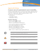
Chapter 1 AP-85 Series Hardware Overview About the AP-85 Series The AP-85 Series consists of resilient, environmentally hardened, outdoor rated, dual-band IEEE 802.11a/b/g devices, which can be configured for deployment as a wireless access point, air monitor, mesh point, or mesh portal. This outdoor access point series is part of Aruba’s comprehensive wireless network solution.
Minimum Software Requirements The AP-85 Series requires ArubaOS 3.2.0 or later. ArubaOS software builds prior to version 3.2.0 do not support the AP-85 Series. If your network currently runs on a software build prior to 3.2.0, you must upgrade the software on your master and local controllers to 3.2.0 or later prior to installing an AP-85 in your existing network.
Hardware Model Overview AP-85 Series Front View The front of the AP-85 Series consists of LED status indicators (see Figure 1). For descriptions of the LEDs and their behavior, refer to LED Status Indicators on page 12. Figure 1 AP-85 Series Front View LED Status Indicators AP-85 Series Rear View The rear of the AP-85 Series consists of four mounting holes (see Figure 2). Refer to Chapter 3, “AP-85 Series Installation” on page 21 for mounting and installation instructions.
AP-85 Series Top View The top of the AP-85 Series consists of four, female N-type antenna interfaces (see Figure 3). Figure 3 AP-85 Series Top View Four, Female N-Type Antenna Interfaces. RADIO 0 supports 2.4 Ghz; RADIO 1 supports 5 GHz The AP-85 Series requires the use of detachable, outdoor rated antennas. Select the correct antenna type to support the required frequency band (2.4 or 5 GHz) and the desired coverage pattern.
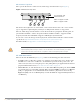
Figure 4 10/100Base-T Fast Ethernet (RJ-45) Port Pin-Out AP-85 10/100Base-T Fast Ethernet (RJ-45) RJ-45 Female Pin-Out 1 2 3 4 5 6 7 8 ETH Tx+ ETH Tx– ETH Rx+ Serial RxD** Serial RGND** ETH Rx– Serial TxD** Serial TGND** Direction Input Output z (POE negative*) (POE negative*) (POE positive*) (POE positive*) (POE positive*) (POE negative*) *POE optional **Serial optional Grounding Point: It is important that the AP-85TX be properly grounded and a grounding point is provided on the bottom of the AP-85
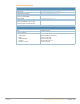
Communication settings for the serial console port are indicated in Table 1. Table 1 Console Terminal Settings Baud Rate Data Bits Parity Stop Bits Flow Control 9600 8 None 1 None z AC PWR 90-228 V~, 500 mA: The AP is capable of accepting AC power at the limits specified on the unit. If the AP-85FX/LX is not connected to a DC power source, the AP must be powered via an AC power source. An outdoor rated, three-wire, 8-foot long AC power cable (wiring harness) is supplied with the unit.
Table 2 AP-85 LED Status Indicators LED Function LAN/Network Link LINK/ACT Status (applicable to the AP-85FX/LX models only) RADIO 0 RADIO 1 RSSI (Radio 0) Radio 0 Status Radio 1 Status RSSI Level for Radio 0 Indicator Status Off Ethernet link unavailable On (Green) 100 Mbs Ethernet link negotiated Blinking Traffic on Ethernet link Off Radio 0 disabled On (Yellow) Radio 0 enabled in WDS mode On (Green) Radio 0 enabled in WLAN mode Off Radio 1disabled On (Yellow) Radio 1 enabled in
| AP-85 Series Hardware Overview Aruba AP-85 Outdoor Access Point Series | Installation Guide
Chapter 2 Outdoor Planning and Deployment Considerations Planning and Deployment Considerations Prior to deploying an outdoor wireless network, the environment must be evaluated to plan for a successful Aruba WLAN deployment. Successfully evaluating the environment enables the proper selection of Aruba APs and antennas and assists in the determination of their placement for optimal RF coverage.
z Industrial RF welding equipment or other Industrial, Scientific and Medical (ISM) equipment that utilizes RF to heat or alter the physical properties of materials z Military, Commercial Aviation or Weather Radar Systems Line of Sight (Radio Path Planning) AP-85 Series access points are capable of performing as one of the following: z Point-to-point wireless distribution system (WDS) bridge z Point-to-multi-point WDS bridge z Enterprise mesh point (MP) z Enterprise mesh portal (MPP) To configur
z Check the topology of the land between the antennas using topographical maps, aerial photos, or even satellite image data (software packages are available that may include this information for your area). z Avoid a path that may incur temporary blockage due to the movement of cars, trains, or aircraft. Antenna Height A reliable wireless bridge or mesh link is usually best achieved by mounting the antennas at each end high enough for a clear radio line of sight between them.
Figure 9 Antenna Height and Line of Sight Radio Line of Sight Visual Line of Sight 3 miles (4.8 km) 2.4 m A 5.4 m B 1.4 m 9m 20 m 17 m 12 m A wireless bridge or mesh link is deployed to connect building A to building B, which is located three miles (4.8 km) away. Mid-way between the two buildings is a small tree-covered hill. From the above table it can be seen that for a three-mile link, the object clearance required at the mid-point is 5.3 m (17.4 ft).
scan your proposed site using a spectrum analyzer to determine if there are any strong radio signals using the 802.11a/b/g channel frequencies. Always use a channel frequency that is furthest away from another signal. If radio interference is still a problem with your wireless bridge or mesh link, changing the antenna direction may improve the situation.
| Outdoor Planning and Deployment Considerations Aruba AP-85 Outdoor Access Point Series | Installation Guide
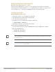
Chapter 3 AP-85 Series Installation Pre-Installation Network Setup Once WLAN planning is complete and the appropriate products and their placement have been determined, installation and initial setup of the Aruba Mobility Controller(s) is required prior to deployment of Aruba Outdoor Access Points. For initial setup of the Mobility Controller, refer to the ArubaOS Quick Start Guide for the software version installed on your controller.
Access Points are radio transmission devices and as such are subject to governmental regulation. Network administrators responsible for the configuration and operation of Access Points must comply with local broadcast regulations. Specifically, Access Points must use channel assignments appropriate to the location in which the Access Point will be used. ! CAUTION 1.
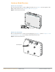
Mounting the AP-85 Preparing the AP-85 for Installation 1. Install the four included mounting bolts (M8 bolts with captive flat washer) into the four mounting holes on the rear of the AP-85 (see Figure 10). Leave approximately two to three threads showing on the mounting bolts. Figure 10 Installing the Mounting Bolts Mounting Holes Mounting Bolts (M8 bolts, 4x) Wall Mounting the AP-85 To wall mount an AP-85: 1.