OWNERS MANUAL HF – Triple Validation Turbidimeter 0-10, 0-100 NTU HF scientific, inc. 3170 Metro Parkway Ft. Myers, FL 33916 239-337-2116 Catalog No. 22634 (5/02) Rev. 2.6 (.
DECLARATION OF CONFORMITY Application of Council Directive Standard to which Conformity is Declared: Product Safety - Tested and passed CE EN61010-1:1990 + A1:1992 (73/32 EEC) Immunity and Emissions – Tested and passed EN61326:1998, Class A Manufacturer’s Name: HF scientific, inc.
Table of Contents Specifications.................................................................................................................................. 1 1.0 Overview............................................................................................................................. 2 1.1 Unpacking and Inspection of the Instrument and Accessories ....................................... 2 1.2 The Display.......................................................................................
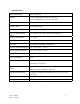
Specifications Measurement Range 0.01 –100.0 NTU Accuracy ±2% of reading plus 0.01 NTU (0-10 NTU) ±5% of reading plus 0.1 NTU (10-100 NTU) Resolution 0.0001 NTU on low readings Response Time Less than 8 seconds Display Liquid Crystal Display Two User Programmable Alarms 120-240VAC 2A Form C Relay with suppressors Analog Output Signals 4 - 20 mA Water Pressure 0.1 - 8 bar (1-116 psi.) Flow Rate 0.5 Liter/min. regulated (.
1.0 Overview The TVT process turbidimeter allows you to measure the turbidity of your process water on-line. The White Light TVT has been designed to meet the design criteria specified by the US EPA on turbidity measurement. The Infra-Red TVT was designed to meet the design criteria specified in ISO 7027 and DIN 27027 for the measurement of the turbidity of a sample. 1.
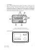
1.2 The Display Figure 1 illustrates all the items that can appear on the display. The upper row of the display (1) is used for reporting the turbidity levels and to provide user guidance in the customer setting routine. The lower row of the display (2) is used to communicate error messages and user guidance. The display has several status indicators (3) that distinguish the operation of the instrument.
Figure 2 illustrates the touch pad. The touch pad has four buttons: MODE, ↵, t, and u. The MODE button is used to cycle between the three operational modes of the instrument: CAL, SETUP, and AUTO (Measurement) mode. The ↵ button enters the option (or mode) that is highlighted or chosen. The tand u buttons are used to scroll through lists and to increase or decrease settings. 2.
3.0 Installation and Commissioning 3.1 Mounting & Site Selection The instrument is designed for wall mounting. If wall mounting is not practical, the instrument can be mounted on any suitable level surface. For ease of service there should be about 45cm (18”) free area above the instrument; this will ensure enough room for calibration and cleaning the optical well. Choose a location that is easily accessible for operation and service and ensure that the front display rests at eye level.
Figure 4: Use of the optional mounting bars to ensure isolation of the 4-20 mA output 3.2 Plumbing The recommended plumbing for the instrument is shown in Figure 3. The instrument is designed to limit the flow to the range of 0.4 – 0.6 liters/minute depending on the system backpressure. Ensure that you supply the instrument with a process flow capable of sustaining this level. Quick-connect fittings are supplied on the inlet and outlet of the instrument; these fitting help speed up calibration procedures.
Pin 1 Pin 2 Pin 3 Pin 4 = = = = 15 –18 VDC (Not Polarity Sensitive) 15 –18 VDC (Not Polarity Sensitive) No Connection No Connection Please observe safe wiring practices. It is recommended that a circuit breaker or switch be placed prior to the power connection to the TVT to allow for service. Relays: The instrument is pre-wired with a 1.8m (6 ft.) long 9-wire relay cable.
4-20 mA: The 4-20 mA output is driven by a 12 VDC power source and can drive recorder loads up to 450 ohms. This 4-20 mA output is isolated from line power and earth ground. Do not run 4-20 mA cables in the same conduit as power. Operation of these alarms is covered in section 8.6 Setting the analog Output (O/P). Ensure each instrument is not powered when connecting the 4-20 mA line.
4.1 Routine Measurement The following steps describe how to measure the turbidity of a sample using this instrument: 1. Apply power to the instrument and allow the unit to warm up (typically 45 minutes – 1 hour on initial commissioning). 2. When a continuous process stream is flowing through the instrument, the instrument will display the measured turbidity level of the sample by displaying it on the LCD screen.
instrument and the calibration procedures. Under normal conditions, re-calibration is recommended at least once every three months1. During calibration, the instrument performs several system self-diagnostics. As such, several warning messages may be displayed. If the instrument detects an irregularity with the instrument (detectors or lamp) a warning message will be displayed on the lower row of the display on exit from the calibration mode.
2. Shut off flow to the instrument. 3. Disconnect the quick connects at the top and bottom to separate the instrument from the process stream, then unscrew and remove the cleanout plug on the instrument. 4. Open the drain valve to allow the process water to drain from the sample well and then close the drain. Capture this water in a container if spilt water is not wanted. 5. Pour 0.
row of the display and then press the ↵ button to initiate calibration. Both the CAL and STORE blocks will flash during the operation and the word YES will change to a count down starting at 90. When the calibration procedure for the 10.0 NTU level is complete the CAL and STORE blocks will stop flashing. You will see the following on the display: 11. Then, you will see the following on the display: 12. Drain the 10.0 NTU calibration standard from the sample well and rinse the well at least twice with 0.
calibrating simply press the ↵ button at this time. However, if you are satisfied and wish to complete calibration on the 0.02 NTU level use the tu arrows to select the word YES on the lower row of the display and then press the ↵ button to initiate calibration. Both the CAL and STORE blocks will flash during the operation and the word YES will change to a count down starting at 90. When the calibration procedure for the 0.02 NTU level is complete the CAL and STORE blocks will stop flashing.
2. 3. 4. 5. 6. 7. record the turbidity reported by the instrument. Take the grab sample and measure its turbidity using your laboratory turbidimeter (contact the HF scientific, inc. customer services department for examples of laboratory turbidimeters). Compare the turbidity reported by the instrument to that obtained in your laboratory. If the readings are very close, then no offset adjustment or calibration is required and you may stop the procedure at this step.
8. 9. 7.0 Select the turbidity level that the instrument reported for your grab sample using the t and u buttons. Once you have set the desired level, press the ↵ button to accept it. This completes the offset configuration. At this point, the instrument will continue to the configuration (setup) mode of the instrument. Instrument Configuration (Range) In order to reduce maintenance during calibration, all TVT’s are shipped from the factory with a range of 0-10 NTU.
Note: To skip the selection of the SETUP mode, simply press the MODE button. 8.1 Displayed Resolution The instrument is equipped with the ability to display several levels of resolution. The instrument can display up to four digits to the right of the decimal place for turbidity readings below 10 NTU. If you feel that the last digit, or two, is not stable then you may adjust the resolution to not show these digits.
Select the correct month by pressing the t or u button to change the displayed month. When you have selected the proper month, press the ↵ button. After pressing the ↵ button, the second number on the upper LCD screen will start to flash: this number corresponds to the day of the month. Select the correct day by pressing the t or u buttons to change the displayed day. When you have selected the proper day, press the ↵ button. 8.
Select the correct minutes level by pressing the t or u button to change the displayed minutes. When you have selected the proper minute’s level, press the ↵ button. 8.5 Programming the Alarms The instrument is equipped with two relays that are designed to operate as two independent programmable alarms. You must input three types of information to fully program each alarm: 1. The alarm function (HI, LOW, or OFF) 2. The alarm set point (level at which the alarm activates) 3.
If the delay off time is set to 5 seconds and the process has exited out of the alarm condition, the alarm will be reset only if the process is out of the alarm condition for a continuous 5 seconds. Otherwise, the instrument will still signal an alarm condition. 8.5.1 Alarm 1 Alarm 1 Function: The “Alarm 1” is highlighted and the lower row of the display indicates the current function of alarm 1 (HI, LOW, or OFF). You can use the toru buttons to cycle through and select the desired function.
Alarm 1 Set Point: Finally, you will be prompted to select the set point for this alarm; this is indicated by “S/P” shown on the lower row of the display. You can select the desired alarm level by using the t and u buttons. Once you have set the desired set point, press the ↵ button to accept it. After you complete the settings for alarm 1 you will be prompted to set up information on alarm #2. 8.5.2 Alarm 2 Repeat the procedure listed in section 8.5.1 to set up the parameters for alarm 2.
Next, you will be prompted with the turbidity level assigned to the 20 mA output level (OHV on the lower row of the LCD display). Select the turbidity level you wish to assign to the OHV using the t and u buttons. Once you have set the desired level, press the ↵ button to accept it. At this point you will be prompted to set up the digital output (PRINT) option. 8.7 Configuring the RS485 I/O Port Automatic/Timed Printouts: After pressing the ↵ button, the PRINT block will be highlighted.
Select the correct baud rate (1200, 2400, 4800, or 9600) for operation of the I/O port by pressing either the t or u button to change the displayed baud rate. When you have selected the proper baud rate press the ↵ button to continue on to configure the security access option. The other parameters for the digital communication are no parity and one (1) stop bit. Note: The information printed out in the timed printout has the format: x.xx NTU dd Mmm yyyy hh:mm.
Pressing the ↵ button will return you back to the normal automatic mode of the instrument. You have now completed the customer selectable parameters section of the instrument. You can enter this menu at any time to re-set, or change, any of the parameters. 9.0 Troubleshooting/System Alarm Relay 9.1 System Warning Message(s) The instrument routinely performs self-diagnostics and will automatically generate warning messages to provide you with specific diagnostic information about the instrument.
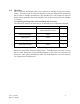
WARNING ASSOCIATED MEANING O-r Sample Over-Range WNG Multiple Warning conditions are met TYPICAL CAUSE to the instrument. If the flow switch is not installed, turn off the option in the setup menu. The sample turbidity level is greater than the instrument will measure (either 11 NTU or 110 NTU depending on your model). A combination of warning conditions has been met. Typically, this condition arises when the setup for the analog output and the flow switch are not set correctly.
10.0 Routine Maintenance 10.1 Cleaning the Optical Chamber (Sample Tube) Proper measurement of turbidity requires that the sample tube be free of debris. Cleaning the sample tube is accomplished by first purging the system: 1. Stop the flow of sample water to the TVT. 2. Remove the cleanout plug and then clean the interior of the sample tube with the brush provided in the HF scientific, inc. calibration kit.
11.0 Accessories and Replacement Parts List The items shown below are recommended accessories and replacement parts. Accessory HF Sure Cal check standard, Reuseable Catalog Number White Light Infrared 19780 19780 Calibration Kit, 0.02 and 10 NTU Standards, 1 liter each 19781 19782 Calibration Kit for extended range calibration. Includes 10 and 100 NTU Standards, 1 Liter each.
12.0 Warranty HF scientific, inc., as vendor, warrants to the original purchaser of this instrument that it will be free of defects in material and workmanship, in normal use and service, for a period of one year from date of delivery to the original purchaser. HF scientific, inc.’s, obligation under this warranty is limited to replacing, at its factory, the instrument or any part thereof.