OWNER’S MANUAL AccUView Wastewater UV Transmission Monitor Catalog No.24743 (1/09) Rev. 2.9 HF scientific 3170 Metro Parkway Ft. Myers, FL 33916 Phone: 239-337-2116 Fax: 239-332-7643 E-Mail: HFinfo@Watts.com Website: www.hfscientific.
DECLARATION OF CONFORMITY Application of Council Directive Standards to Which Conformity is Declared: Product Safety - Tested and passed CE EN61010-1: 1990 + A1: 1992 (73/32 EEC) st - Tested and passed ETL (tested to UL 61010B-1)1 Edition, Dated January 24, 2003 - Tested and passed ETLc (tested to CSA C22.2#1010.
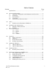
Table of Contents Section Page Specifications .................................................................................................... 1 1.0 Overview & Orientation.................................................................................... 2 1.1 Unpacking and Inspection of the Instrument and Accessories ............. 2 1.2 The Display .......................................................................................... 3 1.3 The Touch Pad .........................................
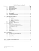
Table of Contents (continued) Section Page 7.7 7.8 7.9 7.10 7.11 7.12 7.13 7.14 7.15 7.16 Extended Settings ................................................................................ 20 Speed of Response............................................................................... 20 LCD Backlight Brightness .................................................................. 21 Ultrasonic Cleaning............................................................................. 21 Pump Period ...........
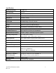
Specifications Measurement Range 0 – 100.0 %T Reproducibility ± 0.1 %T Resolution 0.1 %T Accuracy ± 1.0 %T (30%T to 100%T) Pump Draw 3.6 meters (12 feet) Flow Rate 0.5 – 1.
1.0 Overview & Orientation The AccUView Wastewater process transmission monitor allows for the UV transmission measurement of process water on-line. The sensor features a low pressure lamp operating at 254 nm. The unit includes a sampling pump capable of drawing water from 3.6m (12 feet) down. The entire unit is enclosed in a weather resistant stainless steel enclosure. A unique feature of the instrument is the ultrasonic cleaning. Refer to section 8.1 for more information. 1.
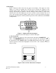
1.2 The Display Figure 1 illustrates all the items that can appear on the display. The upper row of the display (1) is used for reporting the %T levels and to provide user guidance in the customer setting routine. The lower row of the display (2) is used to communicate error messages and provide user guidance. All error messages will be added to a queue along with the units (%T). The display has two icons (3) that are used to indicate the use of access code and offset mode.
1.4 Vapor Purge The AccUView Wastewater sensor is equipped with a continuous vapor purge system. A replaceable desiccant pouch in the lower portion of the instrument dries the air. System heat is used to warm the air. A fan inside the instrument continuously circulates heated dry air around the optical well and the flow through cuvette. This feature eliminates the need for a dry purge line. The AccUView Wastewater Sensor monitors the replaceable desiccant pouch condition continuously.
2.0 Safety This manual contains basic instructions that must be followed during the commissioning, operation, care and maintenance of the instrument. The safety protection provided by this equipment may be impaired if it is commissioned and/or used in a manner not described in this manual. Consequently, all responsible personnel must read this manual prior to working with this instrument. In certain instances Notes, or helpful hints, have been highlighted to give further clarification to the instructions.
3.0 Installation and Commissioning Prior to use for the first time, the supplied desiccant pouch will need to be installed. Refer to section 9.2 Replacing or Installing the Desiccant Pouch. 3.1 Mounting & Site Selection The instrument is designed for wall mounting. For rail mounting, contact HF scientific. Choose a location that is easily accessible for operation and service. Ensure that the front display rests at eye level.
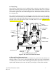
3.2 Plumbing The recommended plumbing for the instrument is shown in Figure 5. The internal bellows pump is capable to drawing water from a depth of 3.6 m (12 ft). To prevent the system from clogging, two strainers are used; a foot strainer at intake line and a Tstrainer inside the instrument. Install the supplied inlet basket strainer onto the inlet line if the flow of the sample water prevents the inlet strainer from remaining submerged, a stand pipe must be used.
3.3 Electrical Connections The electrical connections to the instrument are made through the two terminal boxes. The connections are labeled within the terminal boxes and are self-descriptive (see Figures 6 & 7). Please follow all local and government recommendations and methods for installation of electrical connections to and between the instrument and other peripheral devices. Plugs are inserted into bulkheads when shipped, to ensure a watertight seal.
POWER SUPPLY TERMINAL BLOCK ALARM TERMINAL BLOCK 240 VAC, 2A PUMP TERMINAL BLOCK 12 VDC 4-20ma / RS485 TERMINAL BLOCK POWER CABLE STRAIN RELIEF SENSOR TERMINAL BOX (WITH LID REMOVED) Figure 7: Sensor Terminal Box 3.3.2 RS-485 (optional): The connection for the RS-485 may be made in the sensor terminal box (see figure 7). The RS-485 Modbus or special protocol half-duplex (2-wire) digital interface operates with differential levels that are less susceptible to electrical interferences.
4.0 Operation This process monitor allows for the measurement of the transmission of process water online. Process water is usually reported in units of %T. Readings above 102 %T are indicated by a flashing display. Readings above 100 %T indicate that the current sample is better than the calibration water. Readings above 102 %T will cause an alarm condition to occur where the relay will change to the alarm condition and the 4-20 mA will change to 2 mA. Readings above 110 %T are not possible.
4.2 Warm-up Upon power-up the AccUView Wastewater will require a warm-up period of about 60 minutes. For improved accuracy allow the AccUView Wastewater to complete warm-up time prior to calibrating. During the warm-up period, the display may flash indicating that it has detected a temperature change. It is normal for this to occur during the warm-up period 4.3 Routine Measurement Assuming that the instrument has been wired and plumbed as specified in section 3.
number to be entered. Use the tor u arrows to select the first of the three numbers in the code and then press the ↵ button to accept the first number of the code. Now enter the second number in the code. Proceed as with the first number followed by ↵. Then repeat the process for the third number in the access code, and finish with the ↵ button. If the valid access code has been selected, the instrument will be directed to the calibration mode.
5.0 Instrument Calibration The instrument was calibrated and tested prior to leaving the factory. Therefore, it is possible to use the instrument directly out of the box. Under normal conditions, recalibration is recommended at least once every month. To get the greatest accuracy calibration may be required once per week. Two cuvettes and two flow through units are supplied with the instrument so that they can be exchanged with each other.
5.2 100%T Calibration Error If the screen shown below is displayed after the 100%T calibration, the internal diagnostics have determined that the calibration fluid requires replacement or the flow through cuvette requires replacement. Check the calibration fluid & cuvette, then recalibrate or restore the factory calibration see 6.1 Restoring Factory Settings. The instrument cannot be used without performing one of these operations. To recalibrate press the MODE key and start the calibration sequence again.
6.0 Instrument Offset In certain instances, it may be desirable to use an offset factor to calibrate the instrument rather than performing a physical calibration of the instrument (as described in section 5.1). This procedure is not recommended in lieu of regular instrument calibration but it can be used in situations where the number of instruments used makes regular calibration prohibitive.
add or subtract the value of the offset to the measured %T value. As an example if the AccUView Wastewater measures the process at 92.6 %T but the laboratory instrument read the sample at 92.2 %T, adding an offset of -0.4 would result in the AccUView Wastewater displaying 92.2 % T. Select the desired offset level using the t and u buttons. Once the desired level has been set, press the ↵ button to accept it. 8. This completes the offset configuration. 9.
7.0 Instrument Configuration (CONFIG mode) The instrument has been designed to provide the ability to customize the instrument according to needs at any time during normal operation. This mode has been split into sub-menus to facilitate instrument configuration. This section describes how to use each of the sub-menus to configure the instrument.
The next, prompt will be the level assigned to the 20 mA output level (UPLM on the lower row of the LCD display). Select the %T level to assign to the UPLM using the t and u buttons. Once the desired level has been set, press the ↵ button to accept it. The final prompt for the 4-20 mA setup is for the error level (ERLV). This is the current level that the instrument will output when an error occurs for possible errors see section 10.1. The error level selections are 0.00 mA, 2.00 mA, 4.
To enable the Modbus mode, select ASCII or RTU. For more information refer to the Modbus Manual (Catalog #24570). The manual is also available as a free download from our website at www.hfscientific.com. 7.4 Configuring the Alarm A relay is provided and is designed to operate as an independent programmable alarm. Two types of information must be input to fully program the alarm: 1. The alarm function (HI, LO, or OFF) 2.
7.6 Enabling the Security Access The instrument is equipped with a security access. If this option is turned on, the user is required to input the access code into the instrument to get to any mode other than AUTO. The only code is 333. This code may not be changed. See section 4.4 for more information on this security feature. The security key icon will be visible and flashing on the display whenever the access option is selected using the t or u buttons. (On or OFF). 7.
7.9 LCD Backlight Brightness The LCD backlight brightness may need to be adjusted. This is of particular interest if multiple instruments are located in the same area and it is desired for the entire group to have the same appearance. Ten levels are available. The default brightness is 8. Change the brightness by pressing the t or u button. When the desired brightness has been selected, press the ↵ button. 7.
7.12 Pumping Time This is amount of time in minutes the pump will operate in each pump cycle. The default is set to 5 minutes. If no changes are made to pump settings the pump will run for 5 minutes every 30 minutes 7.13 Settling Time This is the period of time in seconds where the sample is allowed to settle or degas prior to measuring. The default setting is 20 seconds and adjustment is allowed from 1 to 60 seconds. 7.
7.15 Desiccant Alarm When the humidity detector in the AccUView Wastewater indicates that the internal environment is close to the point where humidity could cause condensation, the instrument will display DESC as a warning. If desired, a desiccant warning can activate the alarm and send the 4-20mA to 2mA. To activate the alarm when the desiccant fails, select On in the DESC menu. The default for this menu is OFF.
8.0 Additional Features and Options 8.1 Ultrasonic Cleaning This system is used to continuously clean the flow through cuvette. It is not intended to clean cuvettes that are already dirty, or replace manual cleaning entirely. The system will increase the time between cleanings dramatically. Please note that the system requires the use of a special cuvette. This cuvette must be used for the system to operate correctly.
8.2.2 Simple Communication The AccUView Wastewater can provide basic communications over simple programs such as the Hilgraeve HyperTerminal that is included with most Microsoft Windows packages. The user could also use Visual Basic or other programs. The default communication parameters are 8 bits, no parity and 1 stop bit. These parameters may be changed in the extended CONFIG menu.
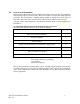
9.0 Routine Maintenance The hydraulic loop through the AccUView Wastewater is fairly simple. This simplicity keeps cleaning intervals to a minimum. The chart below shows suggested maintenance periods. As each installation is different, some maintenance periods will vary. It is recommended to always monitor the flow on a daily basis and replace tubing on annual basis.
The desiccant should be replaced when the instrument displays DESC. A new sealed desiccant pouch and indicator card are available from HF scientific part #21555R. To initially install or remove the old desiccant, simply unscrew the four corner thumbscrews and remove the electronics half of the instrument. Open the bag protecting the new desiccant pouch and replace (or install) immediately.
9.8 System Cleaning The suggested cleaning period is once every three months. As this is very site specific, this period will have to be adjusted as required. Cleaning is recommended with chlorine to remove algae and then a Lime-A-Way to remove calcium and lime. The system should be flushed after cleaning with each solution. Steps: 1. Press the MODE/EXIT key to change the instrument to the SVC mode. This will ensure the pump will not start. 2. Disconnect the main drain and inlet tubings. 3.
10.0 Troubleshooting 10.1 AccUView Wastewater Fault Detection The AccUView Wastewater performs continuous diagnostic monitoring. In the AccUView Wastewater there are three levels of fault detection; warnings, errors and failures. Any faults are displayed in a queue form in the bottom row of the LCD. A warning is simply a screen indication of a problem. No alarm is activated. If the desiccant alarm is turned off and the desiccant becomes saturated, a screen warning of DESC will appear.
10.3 Wiring Diagrams These diagrams show the wiring for the AccUView Wastewater with the Heater Option. For systems without the heater option omit the drain valves, thermostat, heaters and related wiring, and terminal rails. TB2 (B) SOL- PUMP (+) RELAY (COM) SOL+ F2 TB1 (A) N PUMP (+) RELAY (NC) RELAY (NO) TB4 F1 TB3 L 100-240 VAC 47-63 Hz Figure 10: Main Panel Wiring – Heater Option Shown AccUView Wastewater (1/09) Rev. 2.
TO DRAIN SOLENOIDS RED (+) TO PUMP BLUE (COM) BLACK (-) RED (+) L L RELAY (NO) RELAY (COM) RELAY (NC) SOL- PUMP (-) RELAY (COM) PUMP (+) RELAY (NC) RELAY (NO) SOL+ L L BLUE TO HEATER TERMINAL BROWN BLOCK GREEN/YELLOW 100-240 VAC 47-63 HZ 175 VA Figure 11: Power Box Wiring 10.
11.0 Accessories and Replacement Parts List The items shown below are recommended accessories and replacement parts.
12.0 Warranty HF scientific, as vendor, warrants to the original purchaser of this instrument that it will be free of defects in material and workmanship, in normal use and service, for a period of one year from date of delivery to the original purchaser. HF scientific’s obligation under this warranty is limited to replacing, at its factory, the instrument or any part thereof.