OWNER’S MANUAL CLX OnLine Residual Chlorine Monitor HF scientific, inc. 3170 Metro Parkway Ft. Myers, FL 33916 Phone: 239-337-2116 Fax: 239-332-7643 EMail:info@hfscientific.com Website: www.hfscientific.com Catalog #24420 (9/07) REV. 3.
DECLARATION OF CONFORMITY Application of Council Directive Standards to Which Conformity is Declared: Product Safety - Tested and passed CE EN61010-1: 1990 + A1: 1992 (73/32 EEC) st - Tested and passed ETL (tested to UL3111-1), 1 Edition, 1994, w/Bulletin June 5, 1996 - Tested and passed ETLc (tested to CSA C22.2#1010.
Table of Contents Section Page Specifications ....................................................................................................1 1.0 Overview ...........................................................................................................2 1.1 Unpacking and Inspection of the Instrument and Accessories .............2 1.2 The Display ...........................................................................................2 1.3 The Touch Pad ..................................
Table of Contents (continued) Section Page 7.8 7.9 7.10 7.11 LCD Backlight Brightness...................................................................19 RS- 485 Parameters..............................................................................20 Cycle Time ..........................................................................................20 Saving Configuration Settings .............................................................20 8.0 Additional Features and Options ....................
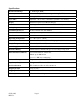
Specifications Measurement Range 0 – 10.00 mg/L (PPM) Accuracy ±5% or ±0.03 mg/L (PPM) for range of 0-6 mg/L(PPM) Resolution 0.01 mg/L (PPM) Cycle Time Adjustable: 90 seconds to 10 minutes (defaults to 2.
1.0 Overview The CLX Online Chlorine Analyzer allows for the reading of chlorine levels of process water on-line. The CLX has been designed to meet the design criteria specified by Standard Methods for the Examination of Water and Wastewater (20th Edition) Method 4500-Cl G. DPD Colorimetric Method. The CLX uses a 515nm LED as the measurement light source. 1.1 Unpacking and Inspection of the Instrument and Accessories The table below indicates the items in the shipment.
1.3 The Touch Pad Figure 2 illustrates the touch pad. The touch pad has six buttons: PRIME, SERVICE, MODE/EXIT, , S and T The MODE/EXIT button is used to cycle between the three operational modes of the instrument: CAL, CONFIG, and AUTO (Measurement) mode. The button enters the option or mode that is highlighted or chosen. The S and T buttons are used to change settings. The PRIME and SERVICE buttons are dedicated controls.
2.0 Safety This manual contains basic instructions that must be followed during the commissioning, operation, care and maintenance of the instrument. The safety protection provided by this equipment may be impaired if it is commissioned and/or used in a manner not described in this manual. Consequently, all responsible personnel must read this manual prior to working with this instrument.
3.0 Theory of Operation The CLX has two solenoid valves, one for sample water (FLOW) and one for draining of the cuvette (PURGE). A third solenoid, along with four check valves forms a reagent pump. Sample water flow is controlled by the FLOW solenoid valve. The PURGE solenoid valve is used to empty the measurement cuvette. The measurement chamber consists of a sample inlet, a purge drain, and an overflow. The reagent is added from the top.
4.0 Installation and Commissioning Prior to use for the first time, one of the reagents (the indicator) will have to be mixed. Refer to section 10.2 Replacing or Installing the Reagents. 4.1 Mounting & Site Selection The instrument is designed for wall mounting. If wall mounting is not practical, the instrument can be mounted on any suitable level surface Choose a location that is easily accessible for operation and service and ensure that the front display rests at eye level.
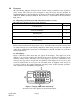
4.2 Plumbing The recommended plumbing for the instrument is shown in Figure 4. The instrument is designed to require very little head pressure to operate, but will need around 34.5kPa (5 PSI). The maximum pressure for proper operation should not exceed 276KPa (40 PSI). The maximum allowable fluid temperature is 40°C (104°F). FLOW ADJUSTMENT SCREW PRESSURE REGULATOR CLX Assembly CABINET VENT DRAIN CONNECTION ACCEPTS 12,7 MM (1/2") I.D. TUBING WATER INLET ACCEPTS 6,35 MM (1/4") O.D.
The fluid waste from drain connection of this instrument contains reagents diluted with large quantities of sample water. HF scientific inc. recommends that operators check with local authorities concerning proper disposal of waste fluids. A ½ “ ID tubing can be placed over the cabinet vent to redirect accidental spills of reagent to a suitable container. 4.3 Setting Flow Rate The flow rate on the CLX was factory adjusted; however, installation variances may affect the flow.
Note: Only qualified electricians should be allowed to perform the installation of the instrument as it involves a line voltage that could endanger life. CAPTIVE SCREW HIGH VOLTAGE COVER POWER CABLE STRAIN RELEIF ANCHOR POWER TERMINAL BLOCK POWER BULKHEAD ALARM #2 TERMINAL BLOCK ALARMS BULKHEAD ALARM #1 TERMINAL BLOCK RS-485 TERMINAL BLOCK COMMUNICATION BULKHEAD 4-20mA TERMINAL BLOCK Figure 5: Electrical Connections for the Instrument 4.4.
The connection block is marked N for Neutral and L for line the third symbol indicates a secure earth ground. The green removable terminal block is suitable for wire gauges 18 to 12 AWG. 4.4.2 RS-485 The RS-485 half-duplex (2-wire) digital interface operates with differential levels that are not susceptible to electrical interferences. This is why cable lengths up to 3000 ft can be implemented.
5.0 Operation The CLX Online Chlorine Analyzer allows for the measurement of the chlorine of process water on-line. The chlorine value of the process water is usually reported in milligrams per Liter (mg/L), these units are equivalent to Parts Per Million (PPM). Readings above 10.00 mg/L are outside the range of this instrument. Readings above 6mg/L may not be within the stated accuracy. 5.1 Routine Measurement First, ensure that all plumbing and electrical connections are complete before continuing.
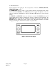
5.2 Security Access Feature The instrument is equipped with a security access code feature that can be activated in the configuration mode. If the security feature is enabled, the screen shown in the illustration below will appear when the MODE/EXIT button is pressed. The security code (333) must be entered to gain access to CAL or CONFIG menus. Notice that the first number in the code is flashing. The flashing indicates that this is the number to be changed.
6.0 Instrument Calibration The instrument was tested prior to leaving the factory. Since it operates from a predetermined calibration curve, no calibration is required. Calibration can easily be performed if required. The method is by comparison against another instrument, such as a laboratory or hand held photometer (such as HF scientific’s Chlorine Pocket Photometer). There are two points of calibration. The slope or gain and the zero (offset).
6.2 Zero (Offset) Calibration Procedure Generally this calibration is only required if readings are expected to be below 1 mg/L or if it is required by a regulatory authority. To perform this calibration, the water supply to the CLX must be changed to chlorine free water such as de-ionized water. This chlorine free water must be run through the instrument for at least 5 minutes prior to using the following procedure. 1. On the CLX, press the MODE/EXIT button once. The screen is shown below. 2.
7.0 Instrument Configuration (CONFIG mode) The instrument has been designed to provide the ability to customize the instrument according to needs at any time during normal operation. This mode has been split into sub-menus to facilitate instrument configuration. This section describes how to use each of the sub-menus to configure the instrument.
The next prompt will be the chlorine level assigned to the 20MA. Select the chlorine level using the S and T buttons. Once the desired level has been set, press the button to accept it. 7.2 Configuring the Error Level In case of an error in the CLX, the 4-20 mA reading can be used to indicate a problem by sending the current to either 4.00 mA, 2.00 mA or 0 mA. If this type of error indication is not wanted, it can be set to OFF. OFF should always be used if the CLX is used to control dosing. 7.
The instrument is equipped with an RS 485 port which operates in Simple bus, a proprietary communication (for HF Online) or Modbus. Prompts will appear for setting the baud rate, the address and the Modbus transmission mode (RTU or ASCII). Select the correct baud rate (1200, 2400, 4800, 9600, or 19200) for operation of the I/O port by pressing the S or T buttons to change the displayed baud rate. Press the button to continue on and select the desired instrument address using the S or T buttons.
programmed alarm level (set point). 3. Error alarm: If there is a system fault or problem the alarm will change states. Alarm Set Point: The level at which an alarm activates is called the alarm set point. On the instrument, the alarm set point is designated as “S/P”. The set point is adjustable to any valid chlorine level over the range of the instrument in steps of 0.01 mg/L. This setting is not available if the Error function is chosen 7.4.
7.6 Extended Settings The last few settings are grouped together to prevent them from being adjusted by accident. To gain access to the extended settings, select On using the S or T buttons and press the button. 7.7 Speed of Response The speed of response for both displayed and output values of mg/L can be adjusted in this menu. Although the default setting is 10, sixty-one (0-60) response speeds are available. The displayed number is a response time, in minutes.
7.9 RS-485 Parameters These menus will only appear if the RS-485 is enabled (see 7.3). The default is 8 Bit, no (nOnE) Parity, 1 Stop Bit. Make selections using the S and T buttons then press the button to move to the next menu. 7.10 Cycle Time The cycle time can be changed using this menu. Please note that changing this menu will directly affect the volume of reagent that will be consumed. The default is set to 150 seconds (2 ½ minutes). Using this setting the reagents will last 30 days.
8.0 Additional Features and Options 8.1 Backlit LCD The backlit LCD allows for easier readability of the LCD display in low light or no light conditions. The backlight is intended for continuous operation. The brightness is adjustable from a menu in the CONFIG mode. 8.2 RS-485 Outputs The CLX has the capability to operate in three different RS-485 modes. Included is a mode for interfacing into the HF Online software package (section 8.2.1 below), a simple communication mode and Modbus communications.
8.2.3 Modbus Communication Modbus protocol communication manual is available HF #24569. This manual is available free online at www.hfscientific.com. 8.3 Remote Panel Meter (Catalog # 19609) The remote panel meter allows for remote indication of the mg/L reading using the 4-20 mA loop of the CLX. No external power is required, as the meter is run off of the 4-20 mA source of the CLX. 8.
9.0 Troubleshooting 9.1 CLX Fault Detection The CLX performs continuous diagnostic monitoring. In the CLX, there are 4 severity levels of fault detection. Level 4, 3 & 2 will allow normal operation, but warn of the problem. Level 1 is an instrument failure and the instrument will not operate. Any faults are displayed in a queue form in the bottom row of the LCD. A level 4 fault is simply a screen indication that one of the alarm levels has been activated.
9.2 Clearing Faults Every time SERVICE mode is exited, all faults are cleared. If the original fault or a new fault occurs, it will be posted. 9.
10.0 Routine Maintenance 10.1 Maintenance Schedule The recommended schedule is shown below. It is important to replace the reagents on a monthly basis to get reliable accurate readings from the CLX. The CLX is shipped with one CLX Tubing/Cuvette kit, HF part # 09950. The kit consists of the following: Part Qty 8 “B” tubings 2 “C” tubings 2 “D” tubings 1 Cuvette CHECK VALVE REAGENT BOTTLE CAP "B" "C" "D" The drawing above shows one complete reagent tubing set.
Flushing the System It is recommended that the tubings replacements be timed with reagent replacement. Press the SERVICE button to stop the water flow. Remove old reagents and discard. Place the inlet tubings in a small container of clean water. Press SERVICE to return to operation mode, press PRIME and then to flush the system with water. Remove the inlet tubings from the water Press PRIME and then to remove most of the water. Note: After a PRIME the CLX will perform a water calibration (WCAL).
Return to Normal Operation Press the SERVICE button to return sample flow to the system. Check for leaks. If a leak occurs press SERVICE again, repair leak and try again. Once the system is operating correctly, return or replace reagents and press PRIME and then one time to restart reagent flow. The system will automatically return to normal operation. Notes: Tubes may darken due to contact with the reagent. This condition does not affect the performance of these parts.
10.2 Replacing or Installing the Reagents Reagent kits are available from HF scientific Inc. Catalog # 09947 for Free Chlorine and Catalog # 009948 for Total Chlorine. There are two reagents required, the buffer and the indicator. The buffer comes premixed and ready to use. Note: The indicator solution must be prepared. Avoid preparation of this reagent in direct sunlight as this may lower the reagent life. Add the contents of one bottle of DPD Powder to a bottle of Free/Total Indicator Solution.
10.4 Instrument Storage If the CLX is relocated or will be inactive for more than 48 hours, remove the reagents. Flush the reagent system as describe in 10.1 Maintenance Schedule. Place the instrument in Service mode to drain the system then remove power by disconnecting the mains power plug. It is usually a good idea to disconnect or shut off the source water. 10.5 Cleaning the CLX Flush the system as mentioned in section 10.1Maintenance Schedule.
11.0 Accessories and Replacement Parts List The items shown below are recommended accessories and replacement parts. Accessory Catalog Number Reagent Kit – Free Chlorine 30 day supply 09947 Reagent Kit – Total Chlorine 30 day supply Operating Manual CLX 09948 25016 Tubing/Cuvette Kit 09950 Replacement Cuvette 25018S Check Valve Set 25017S To order any accessory or replacement part, please contact the HF scientific, inc. Customer Service Department.
12.0 Warranty HF scientific, inc., as vendor, warrants to the original purchaser of this instrument that it will be free of defects in material and workmanship, in normal use and service, for a period of one year from date of delivery to the original purchaser. HF scientific, inc.’s, obligation under this warranty is limited to replacing, at its factory, the instrument or any part thereof.