OWNER’S MANUAL CLX OnLine Residual Chlorine Monitor HF scientific 3170 Metro Parkway Ft. Myers, FL 33916 Phone: 239-337-2116 Fax: 239-332-7643 Toll Free: 888-203-7248 EMail:HFInfo@Watts.com Website: www.hfscientific.com Catalog #24420 (1/12) REV 5.
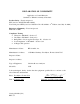
DECLARATION OF CONFORMITY Application of Council Directive Standards to Which Conformity is Declared: Product Safety – Tested and passed: ETL (tested to ANSI/ UL61010-1-2004) Tested and passed ETL (tested to CAN/CSA C22.2 No.61010.1- 2nd Edition, dated July 12, 2004) Emissions & Immunity – Tested and passed: EN61326-1: 2006 Compliance Testing • Vibration to EN 60945 - Section 8.7 • Dry Heat to EN 60945 – Section 8.2 • Damp Heat to Lloyds register Test Spec. No.
Table of Contents Section Page Specifications ....................................................................................................1 1.0 Overview ...........................................................................................................2 1.1 Unpacking and Inspection of the Instrument and Accessories .............2 1.2 The Display ...........................................................................................3 1.3 The Touch Pad ..................................
Table of Contents (continued) Section Page 7.6 7.7 7.8 7.9 7.10 7.11 7.12 7.13 7.14 Extended Settings.................................................................................18 Units of Measurement ..........................................................................19 Averaging and Filtering .......................................................................19 LCD Backlight Brightness ...................................................................20 RS- 485 Parameters................
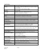
Specifications Measurement Range 0 – 10.00 mg/L (PPM) Accuracy ±5% of reading or ±0.03 mg/L (PPM) whichever is greater for range of 0-6.0 mg/L(PPM) ±10% of reading from 6.01-10.00 mg/L (PPM) Resolution 0.01 mg/L (PPM) Cycle Time Adjustable; 110 seconds to 10 minutes (600 seconds) Note: the system defaults to 2.
1.0 Overview The CLX Online Chlorine Analyzer allows for the reading of chlorine levels of process water on-line. The CLX has been designed to meet the design criteria specified by Standard Methods for the Examination of Water and Wastewater (21th Edition) Method 4500-Cl G. DPD Colorimetric Method. The CLX uses a 515nm LED as the measurement light source. Every effort has been made to ensure the accuracy of this manual.
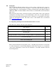
1.2 The Display Figure 1 illustrates all the items that can appear on the display. The upper row of the display (1) is used for reporting the chlorine levels and to provide user guidance in the customer setting routine. The lower row of the display (2) is used to communicate error messages (message queue) and provide user guidance. The display has two icons (3) that are used to indicate the use of access code and offset mode.
2.0 Safety This manual contains basic instructions that must be followed during the commissioning, operation, care and maintenance of the instrument. The safety protection provided by this equipment may be impaired if it is commissioned and/or used in a manner not described in this manual. Consequently, all responsible personnel must read this manual prior to working with this instrument.
3.0 Theory of Operation The CLX has two solenoid valves, one for sample water (FLOW) and one for draining of the cuvette (PURGE). A third solenoid, along with four check valves forms a reagent pump. Sample water flow is controlled by the FLOW solenoid valve. The PURGE solenoid valve is used to empty the cuvette in the measurement chamber. The measurement chamber consists of a sample inlet, a purge drain, and an overflow. The reagent is added from the check valves integrated into the lower portion.
4.0 Installation and Commissioning Prior to use for the first time, one of the reagents (the indicator) will have to be mixed. Refer to section 10.2 Replacing or Installing the Reagents. 4.1 Mounting & Site Selection The instrument is designed for wall mounting. If wall mounting is not practical, the instrument can be mounted on any suitable level surface Choose a location that is easily accessible for operation and service and ensure that the front display rests at eye level.
4.2 Plumbing he recommended plumbing for the instrument is shown in Figure 4. The instrument is designed to require very little head pressure to operate, but will need around 0.34 bar (5 PSI). The maximum pressure for proper operation should not exceed 10.3 bar (150 PSI). The maximum allowable fluid temperature is 40°C (104°F). ONLINE CHLORINE MONITOR CABINET VENT DRAIN CONNECTION ACCEPTS 12,7 MM (1/2") I. D. TUBING PRESSURE REGULATOR WATER INLET ACCEPTS 6,35 MM (1/4") O. D.
The fluid waste from drain connection of this instrument contains reagents diluted with large quantities of sample water. HF scientific recommends that operators check with local authorities concerning proper disposal of waste fluids. This waste fluid must NEVER be reintroduced into the incoming water stream. A ½ “ ID tubing can be placed over the cabinet vent to redirect accidental spills of reagent to a suitable container. 4.
Plugs are inserted into the RS-485 and 4-20mA cable bulkheads when shipped, to ensure a watertight seal. These plugs should be removed and discarded when cabling to either of these connections. The power cable bulkhead will accept cable diameters from 5.8mm (.230 in.) up to 10 mm (.395 in.). All terminals are designed to accept wires in the range of 14-28 AWG. All wires should be stripped to a length of 6 mm (¼”). A strain relief strap is provided to reduce tension on the power terminals.
4.3.3 Relays The Alarm 1 and Alarm 2 relays are mechanical relays rated at 240 VAC 2A. Please note that the relays are labeled NO (Normally Open), NC (Normally Closed) and C (Common). As these alarms are configured fail-safe, the normal condition is with power applied to the CLX and in a non-alarm condition. Operation of these alarms is covered in section 7.4 Configuring the Alarms. The lever operated terminal blocks are rated for wire gauges 28-14. 4.3.
5.0 Operation The CLX Online Chlorine Analyzer allows for the measurement of the chlorine of process water on-line. The chlorine value of the process water is usually reported in milligrams per Liter (mg/L), these units are equivalent to Parts Per Million (PPM). Readings above 10.00 mg/L are outside the range of this instrument. Although the CLX may display above 10.0 mg/L, these readings will not be within the stated accuracy. As the reagents degrade due to aging, readings above 10.
5.2 Security Access Feature The instrument is equipped with a security access code feature that can be activated in the configuration mode. If the security feature is enabled, the screen shown in the illustration below will appear when the MODE/EXIT button is pressed. The security code (333) must be entered to gain access to CAL or CONFIG menus. Notice that the first number in the code is flashing. The flashing indicates that this is the number to be changed.
6.0 Instrument Calibration The instrument was tested prior to leaving the factory. Since it operates from a predetermined calibration curve, no calibration is required. Calibration can easily be performed if required. The method is by comparison against another instrument, such as a laboratory or hand held photometer (such as HF scientific’s Chlorine Pocket Photometer). There are two points of calibration. The slope or gain and the zero (offset).
6.2 Zero (offset) Calibration Procedure Generally this calibration is only required if readings are expected to be below 1 mg/L or if it is required by a regulatory authority. To perform this calibration, the water supply to the CLX must be changed to chlorine free water such as de-ionized water. This chlorine free water must be run through the instrument for at least 5 minutes prior to using the following procedure. 1. On the CLX, press the MODE/EXIT button once. The screen is shown below. 2.
7.0 Instrument Configuration (CONFIG mode) The instrument has been designed to provide the ability to customize the instrument according to needs at any time during normal operation. This mode has been split into sub-menus to facilitate instrument configuration. This section describes how to use each of the sub-menus to configure the instrument.
The next prompt will be the chlorine level assigned to the 20MA. Select the chlorine level using the and buttons. Once the desired level has been set, press the button to accept it. 7.2 Configuring the Error Level In case of an error in the CLX, the 4-20 mA reading can be used to indicate a problem by sending the current to either 4.00 mA, 2.00 mA or 0 mA. The factory default setting is OFF.
Press the button to continue on and select the desired instrument address using the or buttons. Once the selection is satisfactory, press the button. To use the Modbus mode, select ASCII or RTU. Refer to the Modbus Manual available from HF scientific or online at www.hfscientific.com. 7.4 Configuring the Alarms Two relays are provided that are designed to operate as two independent programmable alarms or as a system problem alarm.
Alarm 1 Set Point: This prompt is used to select the set point for this alarm; this is indicated by “S/P” shown on the lower row of the display. Select the desired alarm level by using the and buttons. Once the desired set point has been set, press the button to accept it. 7.4.2 Alarm 2 Repeat the procedure listed in section 7.4.1 to set up the parameters for alarm 2. If a selection was made to turn the alarm OFF, the next selection for the speed of response RESP is shown.
7.7 Units of Measurement The unit of measure can be set to either mg/L (milligrams per liter) or PPM (parts per million). The factory setting is mg/L. Select the desired UNIT using the and buttons and press the button to accept it. mg/L screen PPM screen 7.8 Averaging and Filtering The CLX can display and output averaged readings to help smooth out the response and eliminate large reading variation in rapidly changing processes.
7.9 LCD Backlight Brightness The LCD backlight brightness may need to be adjusted. This is of particular interest if multiple instruments are located in the same area and it is desired for the entire group to have the same appearance. Ten levels are available. The factory setting brightness is 8. Change the brightness by pressing the or button. When the desired brightness has been selected, press the button. 7.10 RS-485 Parameters These menus will only appear if the RS-485 is enabled (see 7.3).
7.11 Cycle Time The cycle time can be changed using this menu. Please note that changing this menu will directly affect the volume of reagent that will be consumed. The default is set to 150 seconds (2 ½ minutes). Using this setting the reagents will last 30 days. Make selections using the and buttons then press the ↵ button. Allowable setting is from 110 to 600 seconds (10 minutes). Reagents have a 30 day life after being mixed regardless of the cycle time setting. 7.
7.13 4mA Adjustment If the 4-20 mA setting is turned ON (7.1 Setting the 4-20 mA Output), the following two menus will appear. The first menu outputs a constant 4 mA while allowing for a small amount of adjustment. The adjustment can be made using the and buttons. This adjustment will allow the operator to make the CLX agree with a PLC or SCADA system. The adjustment limits are ± 200 counts or about ± 0.2 mA.
8.0 Additional Features and Options 8.1 Backlit LCD The backlit LCD allows for easier readability of the LCD display in low light or no light conditions. The backlight is intended for continuous operation. The brightness is adjustable from a menu in the CONFIG mode. 8.2 RS-485 Outputs The CLX has the capability to operate in three different RS-485 modes. Included is a mode for interfacing into the HF Online software package (section 8.2.1 below), a simple communication mode and Modbus communications.
8.2.3 Modbus Communication Modbus protocol communication manual is available HF #24569. This manual is available free online at www.hfscientific.com. 8.3 Remote Panel Meter (Catalog # 19609) The remote panel meter allows for remote indication of the mg/L reading using the 4-20 mA loop of the CLX. No external power is required, as the meter is run off of the 4-20 mA source of the CLX. 8.
9.0 Troubleshooting 9.1 CLX Fault Detection The CLX performs continuous diagnostic monitoring. In the CLX, there are 4 severity levels of fault detection. Level 4, 3 & 2 will allow normal operation, but warn of the problem. Level 1 is an instrument failure and the instrument will not operate. Any faults are displayed in a queue form in the bottom row of the LCD. A level 4 fault is simply a screen indication that one of the alarm levels has been activated.
A level 1 fault is a system fault. This is NOT a problem that the operator can correct, and the unit must be returned to the factory for service (see section 9.5). These failures consist of failures in the CPU, A/D, EEPROM or other devices internal to the instrument. The queued display will show FAIL, the upper display is a five digit code. If this fault occurs, it will affect the 4-20mA and any alarm set for fault detection (Error). The instrument will not operate with this fault.
9.
10.0 Routine Maintenance 10.1 Maintenance Schedule The recommended schedule is shown below. It is important to replace the reagents on a monthly basis to get reliable accurate readings from the CLX. The CLX is shipped with one CLX Tubing/Cuvette kit, HF part # 09950.
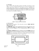
After a PRIME the CLX will perform a water calibration (WCAL). It will take a few minutes to complete this procedure. 3 Month Tubing Replacement The “B” tubings need replacement more often due to the fact that they are subject to wear from the reagent “Pump”. The check valves should not need to be replaced and should be saved. Please note that the check valves are directional and that the “IN” side is smaller in diameter (see drawing).
KNURLED TOP CAP ASSEMBLY "A" OPTICS SYSTEM THUMB SCREW CAP ASSEMBLY "A" PUMP HAMMER AND SPRING CUVETTE RETAINING O-RING REAGENT PUMP ASSY FLOWy INLET CHECK VALVES INLET OUTLET CHECK VALVE DETAIL Figure 7: Reagent Tubing Installation 10.2 Replacing or Installing the Reagents Reagent kits are available from HF scientific for Free Chlorine and for Total Chlorine Refer to section 11.0 Replacement Parts and Accessories for the appropriate Catalog numbers.
Indicator Reagent Preparation Add about 400 ml of deionized water into the indicator bottle. Cap tightly and shake vigorously until the powder is dissolved. Remove the cap and add the contents of the DPD powder bottle (small brown bottle). Cap and shake to fully dissolve the powder. When fully dissolved add enough deionized water to bring the volume in the bottle up to the fill line. Once mixed the reagents have a expected life of 30 days.
10.4 Cuvette Change As recommended in section 10.1 Maintenance Schedule the cuvette should be inspected at monthly intervals and replaced when needed. To replace the cuvette, press the SERVICE key. When HOLD shows on the screen, the system is ready. The cuvette is spring loaded to allow for removal. Leave the cuvette retainer (O-ring) in place while loosening top. Loosen the knurled top until the cuvette pops out. Pull the cuvette retainer down to allow for cuvette removal.
11.0 Accessories and Replacement Parts List The items shown below are recommended accessories and replacement parts. Accessory Catalog Number J.A.W. Reagent Kit – Free Chlorine 30 day supply 09951 J.A.W. Reagent Kit – Total Chlorine 30 day supply J.A.W. Reagent Kit – Free Chlorine 60 day supply J.A.W. Reagent Kit – Total Chlorine 60 day supply J.A.W. Reagent Kit – Free Chlorine 12 month supply J.A.W.
12.0 Warranty HF scientific inc., as vendor, warrants to the original purchaser of this instrument that it will be free of defects in material and workmanship, in normal use and service, for a period of two years from date of manufacture. This warranty includes only instruments coved in this manual manufactured after January 1, 2012. HF scientific inc.’s obligation under this warranty is limited to replacing, at its factory, the instrument or any part thereof.