DRT-100B & DRT-100B RESEARCH TURBIDIMETERS HF scientific, inc. 3170 Metro Parkway Fort Myers,Florida 33916-7597 Phone: (941) 337-2116 Fax: (941) 332-7643 Catalog No.
FOREWORD HF TURBIDIMETERS HF turbidimeters are manufactured to meet design criteria for nephelometers as described in Standard Methods For Examination of Water and Wastewater. HF turbidimeters are approved by the U.S. EPA* as a means to measure the turbidity of potable water, waste water, and other liquids. HF turbidimeters provide a linear display of turbidity, throughout all ranges, in Nephelometric Turbidity Units (NTU).
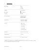
MODEL DRT-100B IDENTIFICATION INFORMATION The DRT-100B may be identified by its catalog number and description listed below: Instrument Catalog†No.
DRT-100B (5/00)
OPERATING INSTRUCTIONS TABLE OF CONTENTS I. SPECIFICATIONS ........................................................................................................... 1 II. INSTALLATION .............................................................................................................. A. Packing List of Contents ............................................................................................ B. Pre-installation Checkout ............................................................
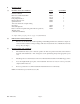
I. SPECIFICATIONS _________________________________________________________________________ 0-1 Ranges NTU 0 - 10 0 - 100 0 - 1000* _________________________________________________________________________ Linearity + 1% of full scale Repeatability + 1% of full scale Sensitivity .01 NTU _________________________________________________________________________ Power Consumption 45 Watts (Nominal) Fuse-0.5A (120V) Fuse-0.
II. INSTALLATION (A) PACKING LIST OF CONTENTS CAT # Instruction Manual Reference Standard 0.02 NTU Accessory Case Lamp Alignment Tool Hex key Wrench 1/16” Spanner Wrench * Recorder and Control output, mating phone plug * Flow through unit Fuse 5 x 20 mm ½A quick acting (220-240 volt operation) Warranty Card (* Included with 20052) 50027 60002 21116 70820 20944 50122 1 1 1 1 1 1 70825 50071 20955 2 1 1 QUANTITY A complete listing of spare parts is on page 11 of this Manual.
III. MEASUREMENT PROCEDURES (A) ADJUSTABLE SET POINT ALARM CONTROL This allows the user to set an alarm where a lamp will be illuminated if the NTU readings should become larger than the value set. The alarm point is set by placing the three position “ALARM” switch labeled “SET”, “NORM”, to the “SET” position. The potentiometer behind the face plate next to the “ALARM” switch is then adjusted until the digital display shows the desired value. The “ALARM” switch is then returned to “NORM”.
Use the following procedure to standardize: 1. Place the Reference Standard in the Optical Well, indexed as described above. 2. Place the front panel Range Switch in the 1 NTU range. 3. Set the Reference Adjust knob, in the left forward corner instrument, such that the display reads .02 NTU. Bottom The turbidimeter’s optical system measures the liquid sample through this section of the Reference Standard, grab sample cuvette or Flow-Thru Vial.
(B) STANDARDIZATION (cont’d) The instrument is now referenced to the factory calibration and unknown samples may be read directly in NTU. For best accuracy, the instrument should be standardized on a scheduled basis. The need to actually adjust standardization will vary depending upon the operational environment. (C) SAMPLE MEASUREMENT 1. Place the sample in the Optical Well. 2. Set the Range Switch located on the front panel to an appropriate range. 3. Read the value on the digital display.
(B) STANDARD FORMAZIN SOLUTIONS Calibration of this instrument is based on Formazin, a material which can be made by synthesis and reproduced repeatedly within one percent. When properly mixed, it is uniform in the number, size and shape of its particles, thus making it an ideal turbidity standard. The unit of measure, and thus the calibration of this instrument is in Nephelometric Turbidity Units (NTU) based on Formazin.
(C) ELECTRONIC CALIBRATION USING HF SECONDARY STANDARDS OR FRESHLY PREPARED FORMAZIN SOLUTIONS Before calibration is attempted, it is important to note that all the calibration potentiometers (reference adjust, linearity, span) are inter-related. That is, adjusting one will also affect the value of the other ranges slightly. 1. Prepare, on the day of calibration, standards of 8 and 800 NTU using the dilution chart in this manual under Section IV. A. 2.
V. FEATURES INCLUDED WITH THE 20052 RESEARCH MODEL (A) ADJUSTABLE SET POINT ALARM CONTROL This feature provides “Dry” contact closure when the measured value exceeds a preset limit. In addition to the dry contact closure, the DRT-100B has a red lamp on the front of the unit that illuminates when the current NTU readings exceed the alarm limit. This limit can be set by placing the three position “ALARM” switch labeled “SET’, “OFF”, “NORM” to the “SET” position.
(E) CONTROL OUTPUT, 4 - 20 MA This feature, which would be used in conjunction with the “Flow Through Unit” feature (Part #50028) provides a control output that varies with changing measured values of a continuous process. The control output is obtained through the mini-phone jack marked “4 - 20 mA” on the rear panel of the instrument. Low and high adjustments for setting desired actuation of the control element for other ranges are located behind the access cover on the front of the instrument. VI.
Figure 2 FOCUS LAMP FOR SHARPEST VERTICAL IMAGE OF FILAMENT CENTERED ON TARGET PT. NO.-70820 Lamp shown here from top view. *NOTE: Dotted line shown represents lamp filament image. VII. SOURCE LAMP REPLACEMENT & ALIGNMENT Turn instrument power OFF and disconnect power source. Remove cover from instrument by unscrewing collar ring on top surface.(Spanner Wrench provided.) Remove the range switch knob (Hex key wrench provided) and six (6) screws from the sides of the cover.
VIII. ACCESSORIES & SUPPLIES PART # DESCRIPTION 20469 PC Board Assy (20012) 20470 PC Board Assy (20052) 20702 Reference Adjust Potentiometer 20973 Fuse, 5 x 20 mm ½A SLO-BLOW (110-120 volt operation) 21001 Lamp Bracket Assy 20850 Photo Diode 21460 Case Accessory (Empty) 60002 Reference Standard 50096 Lamp Assembly 2/pk. 50027 Instruction Manual DRT-100B 50051 Cuvette, Selected, 28 x 70 mm, 3 Pk.
This page was intentionally left blank.
WARRANTY HF scientific, inc., as vendor, warrants to the original purchaser of the instruments to be free of defects in material and workmanship, in normal use and service, for a period of one year from date of delivery to the original purchaser. HF scientific, inc.’s, obligation under this warranty is limited to replacing, at its factory, the instrument or any part thereof.