OWNER’S MANUAL HF scientific– Micro 1000 Laboratory Turbidimeter 0-10,000 NTU HF scientific 3170 Metro Parkway Ft. Myers, FL 33916 Phone: (239) 337-2116 Fax: (239) 332-7643 Toll free: 888-203-7248 Email: HF info@Watts.com Website: www.hfscientific.com Catalog No. 22615 (1/11) Rev 3.
DECLARATION OF CONFORMITY Application of Council Directive: 73/23/EEC Standard to which Conformity is Declared: Product Safety UL3101-1 CSA-C22.2 No. 1010-1-92 EN61010-1: 1993 + A2: 1995 Immunity & EMI EN61326-1: 2006 Manufacture’s Name: HF scientific, inc. Manufacture’s Address: 3170 Metro Parkway, Fort Myers, Florida 33916-7597 Importer’s Name: Importer’s Address: Type of Equipment: Laboratory Turbidimeter Model No.
1. SPECIFICATIONS..........................................................................................................................1 2. Overview..........................................................................................................................................2 2.1. Unpacking and Inspection of the Instrument and Accessories................................................................................ 2 2.2. User Interface ...................................................
10. Accessories and Replacement Parts List........................................................................................25 11. Glossary .........................................................................................................................................26 12. Warranty ........................................................................................................................................27 Rev. 3.
1. SPECIFICATIONS Instrument Conformance Light Source Measurement Options and Ranges NTU FNU EBC NEPHELO FAU Signal Averaging Auto Ranging Accuracy † 0 – 1000 NTU 1000 – 4000 NTU 4000 – 10,000 NTU Repeatability Resolution Response Time Serial Input/Output Certifications Power Supply Display Miscellaneous Specifications Operating Temperature Range Sample Flow Rate Through The Flow Cell Air Purge Shipping Dimensions Shipping Weight Warranty MICRO 1000 Conforms to specifications set forth in EPA method 180.
2. Overview The Micro 1000 process turbidimeter allows you to measure the turbidity of your process water. The White Light Micro 1000 has been designed to meet the design criteria specified by the US EPA on turbidity measurement. The Infra-Red Micro 1000 (Micro 1000 IR) was designed to meet the design criteria specified in ISO 7027 and DIN 27027 for the measurement of the turbidity of a sample. 2.1.
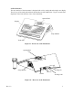
2.2.User Interface The user interface of the instrument is designed with a 6 key touch pad and a single user display. The six keys of the touch pad and their functionality are described below. Figures 1a and 1b are depictions of the front and rear views of the instrument. Optical Well Display Lamp Module Touch Pad Figure 1a - Front view of the Instrument Optical Well Lamp Module Air Purge In RS-232 15VDC Air Purge Out Figure 1b – Rear view of the Instrument Rev. 3.
The ON/OFF key ( ) key is used to turn the instrument ON or OFF. The enter key ( ) is used to accept information. The up and down arrow keys (SandT) are used to set and reset numerical values and to change instrument modes. The left and right arrow keys (◄and►) are used to scroll through lists. In addition, the rear panel of the instrument is designed to provide ready access to the power plug connector, the RS-232 serial port and the dry air purge connector.
4. Routine Operation 4.1. Measurement Principle & Methodology This instrument is designed to measure the turbidity of a sample in nephelometric turbidity units (NTU). In addition, the instrument is capable of measuring in several other standardized scales: Applicable Instrument (s) Scale Definition White Light Infrared Ratio - NTU Turbidity measured via a combination of transmitted and 90° scattered light using the 90° scattered light as the primary detector signal.
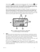
During normal operation, the AUTO block will be highlighted with the current scale displayed on the lower row of the display and the measured reading on the upper row of the display: In certain instances, during normal operation, the instrument will display a row of dashes across the upper row of the display. This indicates that either the instrument is performing an auto-ranging function, or the sample has not yet stabilized (e.g. air coming out of solution in the form of bubbles).
5. Completely fill the rinsed cuvette (from step 4) with the remaining portion (approximately 30 ml) of the grab sample and then cap the cuvette with the black light shield. Ensure that the outside of the cuvette is dry, clean and free from smudges. 6. Place the cuvette in the instrument and index the cuvette to the lowest reading (the displayed turbidity is updated once a second).
4.5. Dry Air Purge System Cold samples, or the continuous flow of cool water through the flow-through cuvette may cause condensation on the walls of the cuvette. This condensation can cause faulty and erratic readings with the instrument. To eliminate this effect, a built in dry air purge system has been designed to optimally circulate air through the optical compartment and prevent this condensation. This is a particularly important feature when using either the pour through or the flow through option.
Under normal conditions, re-calibration is recommended at least once every three months1. You may select a predetermined calibration interval for automatic prompting for calibration: if you exceed the selected calibration interval, the "Cal" block will flash until the instrument is recalibrated. During calibration, the instrument performs several system self-diagnostics. As such, several warning messages may be displayed.
1. Slowly rotate the calibration standard one complete revolution (360°). While rotating the standard, observe the measured turbidity and locate the position of the cuvette having the lowest turbidity reading. 2. With the calibration standard positioned at the location having the lowest turbidity reading, install the Indexing Ring over the black light shield on the standard so that the pointer of the Ring faces forward, toward the operator.
3. When the instrument has completed the calibration, the “Cal” and the “Store” blocks will quit flashing and the lower row of the display should now indicate that the 1750 NTU standard is the next standard to be used for calibration (1.75 K). Press the key to indicate to the instrument that you plan to calibrate on this point. 4. Invert the 1750 NTU calibration standard several times to mix prior to use.Insert the 1750 NTU calibration standard into the sample well and calibrate as before.
6. Insert the 100.0 NTU calibration standard into the sample well and calibrate as before. When the instrument has completed the calibration, , the “Cal” and the “Store” blocks will quit flashing and the lower row of the display should now indicate that the 10.0 NTU standard is the next standard to be used for calibration. 7. Insert the 10.0 NTU calibration standard into the sample well and calibrate as before.
Notes: 6. 1. You must use the 0.02 NTU standard at the beginning and end of the calibration cycle to ensure accurate calibration of the instrument. 2. During calibration, the instrument performs some system self-diagnostics. Several warning or error messages may be displayed. If there is an error in calibration, the associated warning or error message(s) will be displayed in the lower row of the LCD screen. Refer to the section on troubleshooting to determine the cause of the warning or error. 3.
This feature is designed to decrease the sensitivity of the instrument to dissolved materials that may adversely affect a turbidity reading (e.g. dissolve material creating color). Press either the S or T keys to change the operational state of this option in the instrument. When you have selected the desired state press the key 6.3. Selecting Display Resolution The instrument is equipped with the ability to display several levels of resolution (number of digits to the right of the decimal place).
The upper row of the display will indicate the operational status of the security access option (on or off). You can change the operational status of this option using either the S or T keys. Once you have set the desired status, press the key to accept it. If you selected to turn on the security access code, you will need to input an access code to be used for entering calibration and for entering the configuration mode.
This feature allows you to select the function of the serial port on the instrument. There are two options to choose from: Off and Timed Output. Select the RS232 option by pressing either the Sor T keys. When you have selected the proper function, press the key. Off: When the RS232 port is turned “Off” you may obtain a printout of the displayed turbidity level each time you press the key in normal mode.
Select the desired number of days between scheduled calibrations by pressing either the S or T keys to change the displayed day. In normal automatic mode, if you exceed this number of days between calibrations, the Cal block will flash until you re-calibrate the instrument. When you have selected the desired calibration interval press the key. 6.7. Setting the Date (Year, Month and Day) With the Year block highlighted and the year displayed, change the displayed year using either the S or T keys.
Select the correct day by pressing either the S or T keys to change the displayed day. When you have selected the proper day, press the key. 6.8.Setting the Time (Hours and Minutes) After pressing the key, the Time block will be displayed and you will see the time displayed on the upper row of the display in 24-hour format. The number flashing corresponds to the hour. Select the correct hour by pressing either the S or T keys to change the displayed hour.
You may also reach this point by pressing either the ◄ or ► key until the word “END” appears on the lower row of the display. At this point, simply press the key to return to the normal mode. Rev. 3.
7. Troubleshooting 7.1. System Warning Message(s) The instrument generates warning messages to provide you with specific diagnostic information about the instrument. These messages are for your use and do not reduce the performance of the instrument. The following sections outline warning messages that could be observed during normal operation. 7.1.1. Flashing “Cal” block A flashing "Cal" block observed during normal automatic mode indicates that you should recalibrate your instrument.
7.1.3. Other warning messages (W-XX) The following table outlines the general warning messages that could arise (normally after calibration is performed). Rev. 3.
WARNING Rev. 3.2 ASSOCIATED MEANING TYPICAL CAUSE W-01 Lamp Failure The lamp is no longer working, or the light output of the lamp is too low for normal operation. W-02 Transmission detector #1 error Transmission detector #1 failed to report the proper signal levels during calibration (the detector circuitry has failed or calibration was performed with the wrong standards).
7.2. System Error Message(s) The instrument generates error messages when problems are detected during normal operation. When these messages are observed and if you do not understand the instructions shown below, contact the HF scientific Technical Services department to determine a resolution to the problem. The instrument indicates an error message when an "E-XX" is displayed on the lower row of the display.
8.1.Cuvette Cleaning and Care Proper measurement of the turbidity of a sample requires the use of a cuvette that is free of marks, smudges, scratches and any bacterial growth. Any typical glass cleaner can be used along with a lint free cloth, or tissue, to clean the outside of the cuvette. The inside of the cuvette can also be cleaned with any typical glass cleaner.
9. Contacting the HF scientific, inc. Technical Service Department For technical assistance or to order replacement parts please contact the HF scientific Technical Services Department or HF scientific Customer Service Department. HF scientific 3170 Metro Parkway Fort Myers, Florida 33916-7597 Phone: (239) 337-2116 Toll free: 888-203-7248 Fax: (239) 332-7643 Email: HFinfo@Watts.com 10.
11. Glossary Formazin Turbidity Units (FTU): see Nephelometric Turbidity Units Indexing a Cuvette: The United States Environmental Protection Agency (US EPA) recommends that cuvettes used for turbidimeter calibration or sample measurement be indexed. To index a cuvette with a sample in it, slowly rotate the cuvette throughout one complete revolution (360°). While rotating the sample cuvette, observe the display and locate the position that the cuvette is in which provides the lowest turbidity reading.
12. Warranty HF scientific, inc., as vendor, warrants to the original purchaser of the instruments to be free of defects in material and workmanship, in normal use and service, for a period of one year from date of delivery to the original purchaser. HF scientific, inc.’s, obligation under this warranty is limited to replacing, at its factory, the instrument or any part thereof.