OWNERS MANUAL Micro TOL 0-1000 NTU HF scientific, inc. 3170 Metro Parkway Ft. Myers, FL 33916 Phone: 239-337-2116 Fax: 239-332-7643 E-Mail: info@hfscientific.com Website: www.hfscientific.com Catalog No. 24031 Rev. 2.
DECLARATION OF CONFORMITY Application of Council Directive Standard to Which Conformity is Declared: Product Safety - Tested and passed CE EN61010-1: 1990 + A1: 1992 (73/32 EEC) - Tested and passed ETL (tested to UL3111-1) - Tested and passed ETLc (tested to CSA C22.
MICRO TOL (12/04) REV. 2.
Table of Contents Specifications.................................................................................................................1 1.0 Overview............................................................................................................2 1.1 Unpacking and Inspection of the Instrument and Accessories .............2 1.2 The Display ...........................................................................................2 1.3 The Touch Pad ......................................
Table of Contents (continued) 9.0 10.0 11.0 Routine Maintenance .......................................................................................28 9.1 Cleaning the Flow Through Cuvette ...................................................28 9.2 Replacing or Installing the Desiccant Pouch ......................................28 9.3 Replacing the Source Lamp ................................................................29 9.4 Replacing the Battery ....................................................
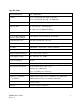
Specifications Measurement Range .01 – 1000.0 NTU Accuracy ±2% of reading plus 0.01 NTU (0-10 NTU) ±5% of reading plus 0.1 NTU (10-1000 NTU) Resolution 0.0001 NTU (below 10 NTU) Response Time 0 - 8 Seconds (0 – 10 NTU Range) 0 – 20 Seconds (0-1000 NTU Range) Display Multi-Line Liquid Crystal Display Two User Programmable Alarms & Analog Output 120-240VAC 2A Form C Relay & 4-20 mA Communications Port Bi-directional RS-485 (optional) Maximum Water Pressure 414 kPa (60 psi.
1.0 Overview The MICRO TOL process turbidimeter allows you to measure the turbidity of your process water on-line. The White Light MICRO TOL has been designed to meet the design criteria specified by the US EPA on turbidity measurement. The infrared MICRO TOL was designed to meet the design criteria specified in ISO 7027 and DIN 27027 for the measurement of the turbidity of a sample. Both models have long life lamps. 1.
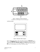
Figure 1 – Display used in the instrument. All items used on the display are shown in this figure 1.3 The Touch Pad Figure 2: The Micro TOL touch pad. Figure 2 illustrates the touch pad. The touch pad has four buttons: MODE/EXIT, ↵, t, and u. The MODE/EXIT button is used to cycle between the four operational modes of the instrument: CAL, CAL OFFSET, CONFIG, and AUTO (Measurement) mode. The ↵ button enters the option (or mode that is highlighted or chosen.
1.4 Vapor purge The Micro TOL is equipped with a continuous vapor purge system. A replaceable desiccant pouch in the lower portion of the instrument dries the air. System heat is used to warm the air. A fan inside the instrument continuously circulates heated dry air around the optical well and the flow through cuvette. This feature eliminates the need for a dry purge line. The Micro TOL monitors the replaceable desiccant pouch condition continuously.
2.0 Safety This manual contains basic instructions that you must follow during the commissioning, operation, care and maintenance of the instrument. The safety protection provided by this equipment may be impaired if it is commissioned and/or used in a manner not described in this manual. Consequently, all responsible personnel must read this manual prior to working with this instrument. In certain instances Notes, or helpful hints, have been highlighted to give further clarification to the instructions.
3.0 Installation and Commissioning Prior to use for the first time, the supplied desiccant pouch will need to be installed. Refer to section 9.2 Replacing or Installing the Desiccant Pouch. 3.1 Mounting & Site Selection The instrument is designed for wall mounting. If wall mounting is not practical, the instrument can be mounted on any suitable level surface.
3.2 Plumbing The recommended plumbing for the instrument is shown in Figure 4. The instrument is designed to require very little head pressure to operate. The flow through cuvette is rated for a flow of 100ml/min. – 6 liters/min. (0.26-1.5 Gal/min), and a maximum pressure of 414 kPa (60 PSI.). The maximum allowable fluid temperature is 50°C (122°F). Figure 4: Recommended Plumbing for the Instrument The instrument is equipped to be plumbed using 4.75 mm (3/16”) ID, 8 mm (5/16”) OD flexible tubing.
3.2.1 Pressurized Systems: For pressurized systems, keep the pressure below 69 kPa (10 PSI) or 7.62 m (25 foot) of head or limit the flow the 1 liter per minute. An inline flow regulator is available from HF scientific inc. catalog number 19778. 3.2.2 Drain Vent: The Micro TOL has been fitted with a drain vent in the “OUT” bulkhead fitting. This fitting allows for atmospheric equalization, thus helping to alleviate bubble formation in the cuvette. In high-pressure systems, minor leakage may occur.
Figure 5: Electrical Connections for the Instrument 3.3.1 Power: The instrument is equipped with a 90-250 VAC, 47-63 Hz switching power supply; please verify that the line voltage falls within these specifications. It is recommended that a circuit breaker be placed prior to the power connection to allow for service. While making your connections, refer to Figure 5. The Micro TOL is not supplied with a power cord. Note: Your Micro TOL is equipped standard with a 4-20 mA output and alarm relays.
4.0 Operation This process turbidimeter allows you to measure the turbidity of your process water online. The turbidity of the process water is reported in Nephelometric Turbidity Units (NTU). Readings above 1000 NTU are outside the range of this instrument. During normal operation, the instrument will have the arrow beside AUTO highlighted with the current scale displayed on the lower row of the display and the measured reading on the upper row of the display (see illustration below).
4.2 Security Access Feature The instrument is equipped with a security access code feature that can be activated in the configuration mode. If the security feature is enabled, the screen shown in the illustration below will appear when you press the MODE/EXIT button. The security code has three numbers that are selectable one at a time. Notice that the first number in the code is flashing; the flashing indicates that this is the number to be changed.
5.0 Instrument Calibration The instrument was calibrated and tested prior to leaving the factory. Therefore, it is possible to use the instrument directly out of the box. Under normal conditions, re1 calibration is recommended at least once every three months . If calibration is not performed, the instrument will continue to monitor the turbidity of the process water with a decreased accuracy.
2. Remove the flow through unit. 3. Insert the requested 1000 NTU standard. Index the standard to the lowest value on the upper display. 4. Press the ↵ button to accept the calibration. 5. The lower display will count down the progress of the calibration step. 6. The lower display will now change to show alternating 10 and ↵, requesting the 10.0 NTU standard. 7. If the alternating 10 and ↵ is not displayed, push the t or uuntil you get this display. 8. Insert the requested 10.0 NTU standard.
Note: During calibration, the fan inside the instrument is turned off to extend the life of the desiccant. The fan will be turned on after returning to the AUTO mode or after five minutes, which ever comes first. It is recommended that the measurement chamber be kept covered during the calibration period and that the flow through cuvette be replaced immediately after the calibration to prevent premature contamination of the desiccant. MICRO TOL (12/04) Rev. 2.
6.0 Instrument Offset In certain instances, you may wish to use an offset factor to calibrate your instrument rather than performing a physical calibration of the instrument (as described in section 5.2). This procedure is not recommended in lieu of regular instrument calibration but it can be used in situations where the number of instruments used makes regular calibration prohibitive.
Select the desired offset level using the t and u buttons. Once you have set the desired level, press the ↵ button to accept it. 7. This completes the offset configuration. 8. At this point, the instrument will continue to the configuration (CONFIG) mode of the instrument or press MODE/EXIT to return to the AUTO mode. 6.1 Indexing Calibration Cuvettes To achieve the greatest accuracy, and account for normal scratches and aberrations in cuvette glass when calibrating, HF scientific inc.
7.0 Instrument Configuration (CONFIG mode) The instrument has been designed to provide you with the ability to customize your instrument according to your needs at any time during normal operation. This mode has been split into sub-menus to facilitate instrument configuration. This section describes how you can use each of the sub-menus to configure your instrument Enter the CONFIG mode of the instrument by pressing the MODE/EXIT button until the arrow beside CONFIG is illuminated, then press the ↵ button.
7.3 Setting the Day and Month After pressing the ↵ button, MNTH will be displayed and you will see a number corresponding to the month. Set the correct month by pressing the t or u button to change the displayed month. When you have selected the proper month, press the ↵ button. After pressing the ↵ button, DAY will be displayed and you will see a number corresponding the day of the month. Set the correct day by pressing the t or u buttons to change the displayed day.
Set the correct hour by pressing the t or u button to change the displayed hour. When you have selected the proper hour, press the ↵ button. After pressing the ↵ button, MIN will be displayed and you will see the current minute of the hour. Set the correct minute by pressing the t or u button to change the displayed minutes. When you have set the correct minute, press the ↵ button. 7.
Delay Off: The turbidity level must not exceed the alarm set point continuously for at least this number of seconds prior to deactivation of the alarm. If the delay off time is set to 5 seconds and the process has exited out of the alarm condition, the alarm will be reset only if the process is out of the alarm condition for a continuous 5 seconds. Otherwise, the instrument will still signal an alarm condition. 7.5.
The current selected number of seconds will be shown. You can select the desired delay off time for this alarm using the t and u buttons. Once you have set the desired delay time, press the ↵ button to accept it. After you complete the settings for alarm 1 you will be prompted to set up information on alarm #2. 7.5.2 Alarm 2 Repeat the procedure listed in section 7.5.1 to set up the parameters for alarm 2.
Select the turbidity level you wish to assign to the UPLM using the t and u buttons. Once you have set the desired level, press the ↵ button to accept it. The next prompt will be for the access code. Refer to section 7.7 Setting the Security Access Option. 7.6 Configuring the RS–485 I/O Port (if equipped) If your instrument is equipped with the option, the following menus will be displayed after the date and time. Automatic/Timed Printouts: After pressing the ↵ button, PRNT will be displayed.
Select the correct baud rate (1200, 2400, 4800, or 9600) for operation of the I/O port by pressing either the t or u button to change the displayed baud rate. When you have selected the proper baud rate press the ↵ button to continue on to 7.7 Setting the Security Access Option. The communication parameters are 8 bits, no parity and 1 stop bit. Note: The information printed out in the timed printout has the format: x.xx NTU dd mm yyyy hh:mm.
Communication Protocol: The originating instrument (master) has a designated address of 00 hex and each instrument has a designated address from 01 hex to FF hex. The communication protocol is as follows: the master computer will send out a 5 BYTE instruction to the instrument to request data and the correct instrument will respond with a 18 BYTE return message.
7.7 Setting the Security Access The instrument is equipped with a security access. If this option is turned on, the user is required to input the access code into the instrument to get to any mode other than AUTO. The only code is 333. This code may not be changed. See section 4.2 for more information on this security feature. The security key icon will be visible and flashing on the display whenever the access option is selected using the t or u buttons. (ON or OFF). 7.
8.0 Troubleshooting & Maintenance 8.1 Micro TOL Fault Detection The Micro TOL performs continuous diagnostic monitoring. In the Micro TOL there are three levels of fault detection; warnings, errors and failures. A warning indicates that there is a system problem that does not interfere with the operation of the instrument and can be corrected by the operator. These warnings consist of 4-20 mA loop open (MA) if equipped, and desiccant replacement required (DESC).
8.3 Diagnostic Chart Symptom Cause Cure Lower display shows MA 4-20 mA loop open Lower display shows DESC Desiccant pouch bad Lower display shows CAL Lower display shows LAMP Calibration failure Lamp failed Lower display shows FLOW Sample flow has stopped Lower display shows FAIL Readings are higher than expected Major system fault (1) Bubbles in solution Check wiring. See sections 3.3.4 and 7.5.3 Change desiccant pouch. See section 9.2 Refer to sections 5 and 6.1 Replace lamp.
9.0 Routine Maintenance 9.1 Cleaning the Flow Through Cuvette Measurement cuvettes used for both grab sample and the flow though should be clean and free of marks or scratches. Cleaning is accomplished by cleaning the interior and exterior with a detergent solution and then rinsing several times with distilled or deionized water. The cuvette can be replaced by first shutting off the flow using the provided shutoff clamp; unscrewing the old cuvette and replacing with a fresh clean one. 9.
9.3 Replacing the Source Lamp The source lamps in the Micro TOL’s are designed for long life. The IR lamp is rated for 10 years and the white light version is rated for 7 years. If your lamp should need replacement, we recommend you call HF Customer Service Department for assistance. 9.4 Replacing the Battery The Micro TOL uses a 10-year life lithium battery as a backup for the contained real-time clock chip. This battery is non-rechargeable, but should last the life of instrument.
11.0 Warranty HF scientific, inc., as vendor, warrants to the original purchaser of this instrument that it will be free of defects in material and workmanship, in normal use and service, for a period of one year from date of delivery to the original purchaser. HF scientific, inc.’s, obligation under this warranty is limited to replacing, at its factory, the instrument or any part thereof.