MicroTUV ONLINE UV TRANSMISSION ANALYZER OPERATION & MAINTENANCE MANUAL Catalog #22814 (1/03) HF scientific, inc.
TUV (1/03) REV. 0.
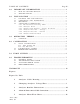
TABLE OF CONTENTS 1.0 I M P O R T A N T I N F O R M A T I O N .......................................................... 1 1.1 1.2 2.0 P A C K I N G L I S T F O R T H E TUV........................................................ 2 U N P A C K I N G A N D I N S P E C T I O N ......................................................2 M O U N T I N G ........................................................................................ 2 A N A L Y Z E R C O N N E C T I O N S .................................
TUV (1/03) REV. 0.
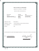
DECLARATION OF CONFORMITY Application of Council Directive: 89/336/EEC Standards to which Conformity is Declared: Product Safety UL3111-1 CSA-C22.2 No. 1010-1-92 CE EN61010-1:1993 (73/23 EEC) Immunity EN50082-1:1997 IE801-2 IEC801-3 IEC901-4 EMI EN55011 Group 1Class A Per 50081-2:1994 FCC Part 15 Class A Manufacturer’s Name: HF scientific, inc.
TUV (1/03) REV. 0.
1.0 IMPORTANT INFORMATION 1.1 HOW TO USE THIS MANUAL This equipment, while sophisticated, has been designed for simple and easy operation. In keeping with that philosophy, this TUV Analyzer user’s manual has been written to simplify all steps in the procedures that follow. THE MOST IMPORTANT ASPECT OF THIS MANUAL IS THAT YOU, THE USER, READ IT IN ITS ENTIRETY AND REFER TO IT OFTEN.
2.0 INSTALLATION 2.1 PACKING LIST CONTENTS QUANTITY Mounting Bracket - installed RS-485 Interface - installed O & M Manual Power Cord - installed 1 1 1 1 A complete listing of spare parts appears on page 9 of this manual. 2.2 UNPACKING AND INSPECTION Use extreme care when unpacking your TUV Analyzer and check that all of the contents are included. Check for any damage that may have occurred during shipping.
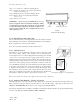
To remove the access cover: Step 1) Loosen the two Analyzer clamping knobs. Step 2) Swivel the Analyzer top forward, such that the back is now facing you. Step 3) Retighten the two Analyzer clamping knobs. Step 4) Remove the 6 screws that retain the black access cover. Step 5) Remove access cover. WARNING: Do not restore power until the access cover has been replaced and secured. When routing the cabling for the following sections, allow enough excess cable length to swivel the Analyzer upside down.
2.4.4 Analyzer Recorder - Voltage Recorder output voltage is selected at the terminal block labeled ANALOG VOLTAGE (J6). Only one of these voltages is to be selected at any time. The recorder load for each voltage is: Terminal 1 0 - 10V 50000 ohms or greater Terminal 2 0 - 1V 5000 ohms or greater Terminal 3 0 - 100mV 500ohms or greater Terminal 4 Common 2.4.5 Analyzer Recorder - Current A 4 - 20 mA current output is available. The connections are made at the terminal block labeled Analog 4 20 mA (J5).
3.1 START UP NOTE: It will be necessary to verify each of the user settings, in the Analyzer, and/or change some, when starting the unit for the first time. The Analyzer screen should respond per the Menu Guide. Refer to Figure 5. While the screen of the Analyzer will start to indicate the % Transmission until the system is calibrated, the reading may not be accurate.
4.2 CALIBRATION ALARMS Cont'd A: The Analyzer will go to an alarm menu and indicate “100% T water out”, shut the Sensor/Sampler pump off and the 4-20 mA will "hold" the last valid reading. Or B: The Analyzer and Sensor/Sampler will continue to operate and ignore the attempted calibration. The Analyzer will show a banner displaying the problem and the time and date of the problem. Please note that while in the Graphic screen, the word MEMORY will be displayed, flashing beside the % T reading.
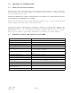
6.0 TROUBLESHOOTING 6.1 GENERAL NOTES Service and Technical Support are available from HF scientific, inc. 3170 Metro Parkway, Fort Myers, Florida 33916-7597, Phone (239) 337-2116, Fax (239) 332-7643. 6.2 TROUBLESHOOTING GUIDE The following table will supply fundamental troubleshooting information. The guide assumes that the controls GUIDE TO FUNDAMENTAL TROUBLESHOOTING and functions of the instrument are used correctly.
6.3 ANALYZER ERROR CODES The following are the error codes that may be indicated on the analyzer. The Analyzer switching to the Error Code page and placing an X beside the fault will indicate the particular problem. During this time the analyzer is not taking readings although the Sensor/Sampler may be operating properly. After correcting a fault, press the “alarm” key on the analyzer to restart the system.
6.4 REPLACEMENT PARTS Catalog No. Description 20955 Fuse, 1/2 amp Fast Acting 5 x 20 mm (240V) 20815 Wire Shielded RS-485 (per foot) 20956 Fuse, 1amp Fast Acting 5 x 20 mm (120V) NOTE: For any other parts not shown here, please contact HF scientific Service Department. TUV (1/03) REV. 0.
XX.XX=INCHES (XX)=mm Figure 3 Analyzer Outline Dimensions TUV (1/03) REV. 0.
TUV (1/03) REV. 0.
Figure 5 Analyzer Menu Flow Chart TUV (1/03) REV. 0.
WARRANTY HF scientific, inc., as manufacturer, warrants to the original purchaser of the instruments to be free of defects in material and workmanship, in normal use and service, for a period of one year from date of delivery to the original purchaser. HF scientific, inc.'s, obligation under this warranty is limited to replacing, at its factory, the instrument or any part thereof.