
User's Manual


HF-LPX30 Series Low Power WiFi Module User Manual
Shanghai High-Flying Electronics Technology Co., Ltd(www.hi-flying.com) - 11 -
High-Flying strongly suggest customer fan out this pin to LED.
PWM function:
PWM0~PWM3 100ns period(if duty is from 0~255, then the maximum frequenry is
10M/256=39KHz), PWM4 support 800ns period.
Due to PWM pin is internal weak pull-up. So when these pins are used for LED bulb
application, suggest to add strong pull-down resistor to revent the lulb on when boot.
Note:nReload pin is also used for special function, when use this pin for PWM bulb
application and add external pull-down resistor, this will cause the module wait 1 second
when bootup(wait “space” key to etner bootloader). Contact us to provice special
bootloader in order to remove this wait time.
UART1 Debug :
1. Is used for debug log or firmware program, baud rate 921600.
2. Can be used for communication in SDK.
1.2.2. Electrical Characteristics
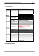
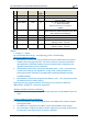
Table3. Absolute Maximum Ratings:
Parameter Condition Min. Typ. Max. Unit
Work temperature range -40 105 °C
Maximum soldering temperature IPC/JEDEC J-STD-020 260 °C
ESD (Human Body Model HBM) TAMB=25°C 2.5 KV
ESD (MM) TAMB=25°C 0.25 KV
Table4. Power Supply & Power Consumption:
Parameter Condition Min. Typ. Max. Unit
Operating Supply voltage 2.9 3.3 4.2 V
Supply current, peak Continuous Tx 260 mA
Supply current, STA No data transfer 27 mA
Supply current, STA Continuous data transfer 35 mA
Supply current, AP 80 mA
GPIO sink current GND+0.5V 3 mA
GPIO pull current VCC-0.5V 3 mA