
User's Manual
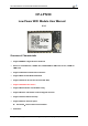

HF-LPX30 Series Low Power WiFi Module User Manual
Shanghai High-Flying Electronics Technology Co., Ltd(www.hi-flying.com) - 9 -
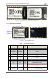
Figure 1. HF-LPT230-1 and HF-LPT230-0 Appearance
1.2.1. HF-LPT230 Pins Definition
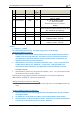
Figure 2. HF-LPT230 Pins Map
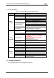
Table2. HF-LPT230 Pins Definition
Pin Describtion Net Name Signal
Type
Comments
1 SPI_MOSI SPI_MOSI O GPIO12,
2 SPI_CLK SPI_CLK I/O GPIO4,
3 SPI_MISO SPI_MISO I GPIO7
4 SPI_CS SPI_CS I/O GPIO5,
5 UART0 UART0_TX O,PU 3.3V UART0 Communication Output
GPIO2
6 UART0 UART0_RX I 3.3V UART0 Communication Input
GPIO1
7 UART0_CTS UART0_CTS I/O GPIO22, PWM0
8 UART0_RTS UART0_RTS I/O,PU GPIO23, PWM1
9 ADC ADC I/O,PU GPADC0,ADC function
10 Module Reset EXT_RESETn I,PU
“Low” effective reset input. There is RC reset
circuit internally. External pull-up resistor is not
allowed.
11 Module Boot Up
Indicator
nReady O “0” – Boot-up OK;
“1” – Boot-up No OK;