
User's Manual Part 3


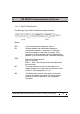


Table Of Contents
- Page 1
- Page 2
- Page 3
- Page 4
- Page 5
- Page 6
- Page 7
- Page 8
- Page 9
- Page 10
- Page 11
- Page 12
- Page 13
- Page 14
- Page 15
- Page 16
- Page 17
- Page 18
- Page 19
- Page 20
- Page 21
- Page 22
- Page 23
- Page 24
- Page 25
- Page 26
- Page 27
- Page 28
- Page 29
- Page 30
- Page 31
- Page 32
- Page 33
- Page 34
- Page 35
- Page 36
- Page 37
- Page 38
- Page 39
- Page 40
- Page 41
- Page 42
- Page 43
- Page 44
- Page 45
- Page 46
- Page 47
- Page 48
- Page 49
- Page 50
- Page 51
- Page 52

Hi-G-Tek Ltd. Microelectronics & Asset Tracking Technology
123
6
RS 485/232 Communication Protocol
6.4.2.2. R_Status Field Structure
The READER's STATUS field is 4 bytes.
Byte A Byte B Byte C Byte D
Byte A represents the status of the main motherboard MCU.
The other bytes represent the RF modems' status.
In a general Reader response the R-Status reply contains
bytes A&B only.
In a GET Status command, the reply contains all the R-Status
bytes.
Byte A:
7 6 5 4 3 2 1 0
LCK 485 PCR PER VCCERR VBERR PMC EDC
Where:
LCK
485
PCR
If the response shows 0, the READER's parameters
are locked.
If the response is 1, the READER's parameters
are unlocked.
If the response is 0, the READER is using RS-232
mode for communication.
If the response shows 1, the READER is using
RS-485 mode for communication.
If the response shows 0, the parameters in the MCU's
2
E ROM are OK.
If the reponse is 1, parameters were corrupted and
successfully restored.