Shenzhen Hi-link Electronic co.,ltd HLK-B10 Serial port -Bluetooth Transmission Module User manual Version:V1.0 Revise Date:2019-8-12 Rights reserved@ShenZhen Hi-link Electronic co.
CONTENT 1. BRIEF INTRODUCTION...................................................................................................... 3 2. PIN DEFINITION.................................................................................................................. 4 3. TYPICAL APPLICATION CIRCUIT.................................................................................... 6 4. BASIC FUNCTIONAL DESCRIPTION............................................................................... 6 4.1.
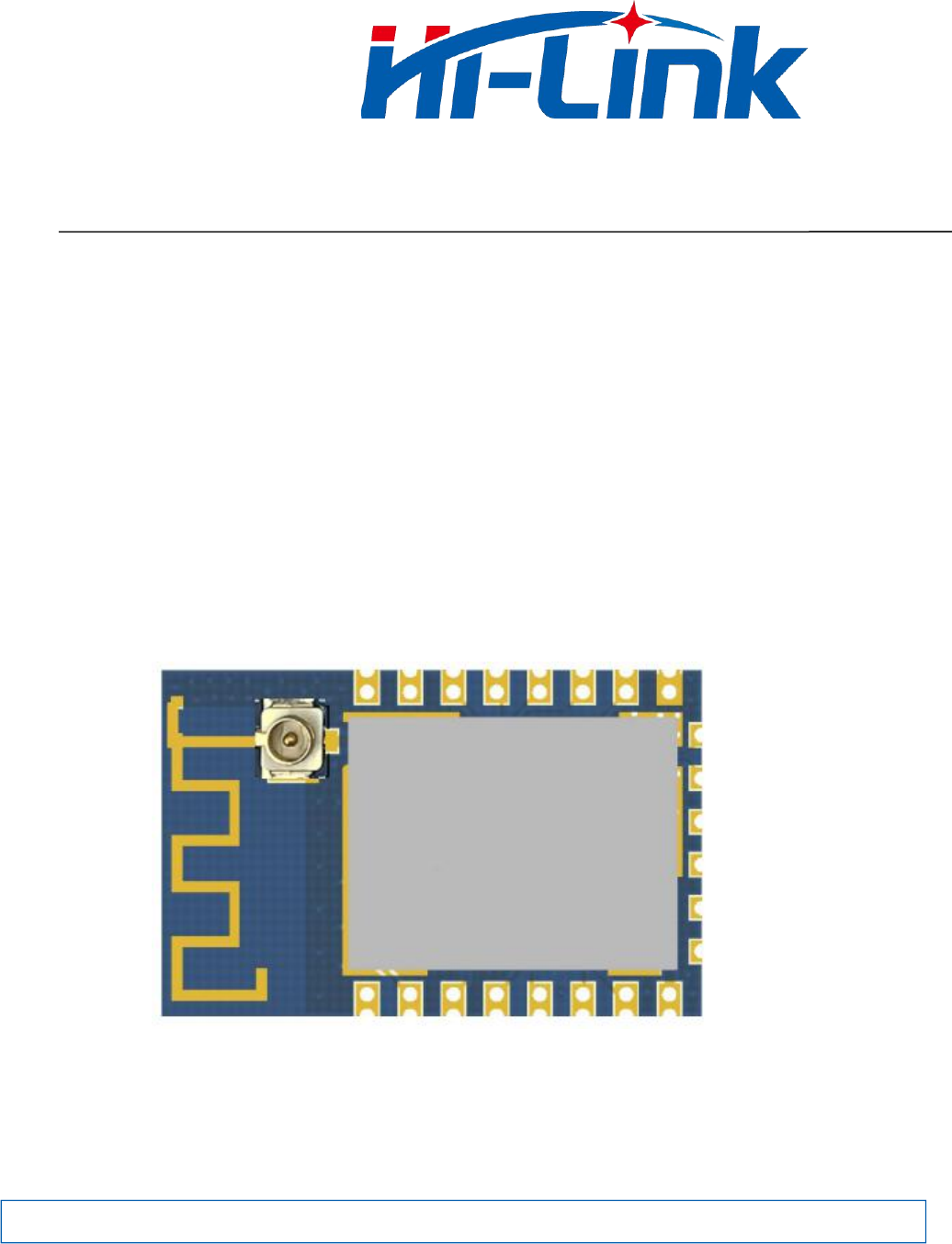
HLK-B10 USER MANUAL 1. Brief Introduction HLK-B10 is a single-mode BLE5.0 Bluetooth transmission module developed by Hi-Link Electronics. It integrates Bluetooth radio frequency chip and a small number of peripheral devices, embedded in 32-bit MCU,500KB flash memory with low power consumption, 64KB SRAM and rich peripheral resources. Meet to Bluetooth 5.0 specification, it can be used as Bluetooth slave device and connected by various Bluetooth host devices.
HLK-B10 USER MANUAL 2. Pin Definition Pin Symbol IO type Function 1 RST AO Module reset input pin,Low level efficiency 2 P07 I/O GPIO7 3 P31 I/O ADC/CH1 4 P10 I/O PWM[0](20mA) 5 P11 I/O Keystroke input pin,Low level efficiency 6 P12 I/O PWM[2] 7 P13 I/O PWM[3] 8 3.3V P Module power supply 3.
HLK-B10 USER MANUAL Pin Symbol IO type Function 15 GND P Power reference place 16 P02 I/O State indicate LED output,Low level efficiency 17 P03 I/O GPIO3 18 P04 I/O GPIO4 19 P05 I/O GPIO5 20 P06 I/O GPIO6 21 RXD I/O UART input 22 TXD I/O UART output Illustration: P represents power pin, I/O represents an input / output pin, AO represents an analog input and output pin. 3.
HLK-B10 USER MANUAL 4. Basic Functional Description 4.1. Two working states of the module HLK-B10 module has two working states: transmission mode and AT command mode. In AT command mode, the command can be sent to the module through serial port to configure the parameters of the module and query the information of the module. In transmission mode, the module will transmit the serial port data and Bluetooth connection data in two-way.
HLK-B10 USER MANUAL mode; Long press(More than 6s),release the button when the status LED starts flashing, the module will restore the default settings, and automatically restart. 4.3. Switching Between Transmission and AT Command Mode 4.3.1. From transmission mode to AT command mode There are two ways to switch the transmission to AT command mode: key mode: Pull down the fifth pin 50ms~1s,The module immediately enters the AT command mode.
HLK-B10 USER MANUAL 5. AT command 5.1. AT command format Format the class command:AT+=<...> X represents the name of the parameter to set,…represent Parameter Value Set a successful return value: Set return value for failure or format error: AT+=<...> OK AT+=<...> ERROR example: send out:AT+DEVNAME=HLK-B10 received:AT+DEVNAME=HLK-B10 OK Query class command format:AT+=? x represents parameter name of the query,… represent parameter value。 Returned value : AT+=? <...
HLK-B10 USER MANUAL AT+TS Send out:AT+TS=1 Restore to transmission mode received:OK Set or query module serial port baud rate AT+BAUDRATE Default baud rate:115200 Send out:AT+BAUDRATE=115200 received:OK Send out:AT+BAUDRATE=? received:115200 AT+DEVNAME Set or query the (Bluetooth) name of the module Send out:AT+DEVNAME=test123 Default:HLK-B10_**** received:test123 received:OK Send out:AT+DEVNAME=? Send out:AT+LINKS=? //connecting,MAC with Bluetooth host AT+LINKS Query module Bluetooth connect
HLK-B10 USER MANUAL test Demo program. 7. Test Tools and Methods 7.1. Test board Users can choose our special test board to quickly start testing and using the HLK-B10 module。 The test board is directly powered by USB, which is provided with a USB to serial port function.
HLK-B10 USER MANUAL When the mobile phone APP and the module establish the Bluetooth connection, the data sent in the mobile phone APP is forwarded to the serial port of the module as it is, and the data sent to the module serial port will be forwarded to the mobile phone APP as it is. 7.3.
HLK-B10 USER MANUAL When the connection is successful, the module's state LED becomes connected; At this time, the data can be sent to the module serial port in the serial port debugging tool on the computer, and the sending content will be received and displayed by the mobile phone APP as it is; Send data to the module from the penetration test APP on the mobile phone, and the sent content will be received by the module as it is and output to the module serial port.
HLK-B10 USER MANUAL Module serial port 8. Mobile phone end Revised Record Date Version Modify content 2019.8.12 1.
HLK-B10 USER MANUAL 9. Technical Support and Contact Information SHENZHEN HI-LINK ELECTRONIC CO.,LRD ADD : 3F,Cai Yue Building West, No.24 Liu Xian Avenue, Long Hua district, Shenzhen 518131 TEL:0755-23152658/83575155; WEB: www.hlktech.
2.2 List of applicable FCC rules FCC Part 15.247 2.6 RF exposure considerations This module certified that complies with RF exposure requirement under 5mm RF distance. 2.8 Label and compliance information FCC ID label on the final system must be labeled with “Contains FCC ID: 2AD56HLK-B10” or “Contains transmitter module FCC ID: 2AD56HLK-B10”. 2.9 Information on test modes and additional testing requirements Contact ShenZhen HaiLingKe Electronic co.
FCC Warning This device complies with Part 15 of the FCC Rules. Operation is subject to the following two conditions: (1) This device may not cause harmful interference, and (2) this device must accept any interference received, including interference that may cause undesired operation. NOTE 1: This product has been tested and found to comply with the limits for a Class B digital device, pursuant to Part 15 of the FCC Rules.