
User's Manual


____________________________________________________________________________________________
HID Corporation 9292 Jeronimo Road Irvine, CA 92618 USA TEL (949) 598-1600 (800) 237-7769 FAX (949) 598-1690
Web page, E-mail -www.hidcorp.com ProxPro Reader Installation Manual 5355A-900 Rev M 3 of 11
descriptions are on the PCB guard in the reader. Connect the drain line of the shield to terminal 2 (Power
Supply Ground). Terminal 5, Data Return, is to be connected to the ground of the Host if the power supply
ground is not common with the Host. The opposite end of the drain line should be cut flush with the jacket
and left disconnected.
6. If the
tamper feature
is available on the Host, connect the tamper switch using the connections
recommended by the Host documentation. The switch is a single pole, double throw. When the inner reader
cover is removed, the tamper switch is released. The TB1 connections to the tamper switch are pins 10 and
11. Pin 10 is the common contact of the switch and pin 11 is either the normally open or closed. Jumper P3
selects the contact of the tamper switch, either the normally closed or the normally open contact. The
default position is P3 across pins 1 and 2. This selects the normally open contact on TB1 pin 11. If the
normally closed contact is required, move P3 across pins 2 and 3. (Note - “normally open and normally
closed refer to the Pin 11 status while the cover is removed.) The contacts are rated for 100mA at 35 VDC.
7.
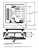
Mount the base
of the reader that holds the electronics to the gang box or surface using the two holes
located on the center axis of the reader. Two #6-32 x 1 inch screws are provided for mounting to a gang
box or metal surface.
8. Set the DIP switches according to the table in the section,
DIP Switch Settings
.
9. Place the jumper on P1 between pins 1 and 2 when
mounting to a metallic surface
or to a junction box
with a metal cover plate. Otherwise, the jumper should be between pins 2 and 3, the default position.
10. After wiring the Reader and power supply, the Reader is ready to be tested.
Power up the Reader
and the
LED and Beeper will flash and beep 3 times in a sequence of two short delays and one long delay. This
indicates that the micro-controller unit is working properly.
If the switches have been set for external control
only, the Reader will 3 shorts and a long. Present an ID card to the Reader and the LED should momentarily
turn green, indicating a read of the card. If the Reader LED is controlled by the Host refer to the Host
description of the LED operation.
11.
Replace the top cover
and face plate.
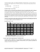
Standard Wire Connections
TB1
1 2 3 4 5 6 7 8 9 10 11
+DC Ground Data0/
Data
Data1/
Clock
Shield
Ground
Green
LED
Red
LED
Beeper Hold/
Card
Present
Tamper
Common
Tamper
Select
Red Black Green White Violet Orange Brown Yellow Blue -- --
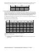
Buffered Direct Wire Connections – Option D
10 11 E1 E2 E3 E4 E5 E6 E7 E8 E9 E10
Tamper
Common
Tamper
Select
+DC Ground Row 1 Row 2 Row 3 Row 4 Column
1
Column
2
Column
3
Select
Low
Red /
Black
Red /
Green
White /
Red
White /
Black
Gray Violet Red /
Yellow
Pink Tan White /
Blue
White /
Green
White /
Yellow
Direct Wire Connections – Option S
TB2
1 2 3 4 5 6 7
Row 1 Row 2 Row 3 Row 4 Column
3
Column
2
Column
1
Red Black Green White Drain Orange Brown