
User's Manual


____________________________________________________________________________________________
HID Corporation 9292 Jeronimo Road Irvine, CA 92618 USA TEL (949) 598-1600 (800) 237-7769 FAX (949) 598-1690
Web page, E-mail -www.hidcorp.com ProxPro Reader Installation Manual 5355A-900 Rev M 6 of 11
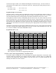
Switch 1-1 Hardware Identity
When set in the "on" position the unit is configured for "Wiegand" interface. The "off" position configures the unit
for "Clock and data" interface.
Switch 1-2 Audible Tone Control
The Audible Tone (Beeper) may be enabled or disabled to sound when an access card is read. When enabled,
the audible tone is sounded when the a card is successfully read. When the Beeper is disabled, the only
method to activate the Beeper is to use the external Beeper control line. The Beeper will turn on when the
control line is switched to ground. Switch 2 in the "on" position enables the audible tone (the default).
Switch 1-3 Green LED Control
The Green LED can be configured to turn on, or not turn on when an access card is read. Switch 3 in the “off”
position selects the Green LED to be turned on (the default).
Switch 1-4 Keypad Operation
The keypad inputs may be processed by the reader or may be connected directly to the Host. When the
keypad inputs are processed by the reader, the reader scans the keypad and outputs the keypad entries over
the "Wiegand" interface. When the keypad is connected to the Host, the Host determines which key is being
entered. Switch 4 is in the "on" position for the default mode (the keypad inputs are processed by the reader).
Switch 1-5 Single / Dual LED Control
In Single LED Control the LED is Red. When an access card is read, the LED toggles Green, and then back to
Red. Grounding the Green LED Control line will change the LED from Red to Green. The reader maybe
configured so the Green LED is externally controlled independently from the Red LED. This is referred to as
Dual LED Control. When the Red or Green LED Control line is switched to ground, the respective LED is
turned on. If both LED’s are on, the LED appears to glow amber. Switch 5 in the “off” position selects Single
LED Control (the default).
Switch 1-6 and 1-7 Data Output Biasing
The data outputs may be configured as open collector or biased at 5VDC through 1k Ohm resistors by the
reader. The default (standard) configuration is output biasing, with switches 6 and 7 "on" . Note: When the
outputs are configured as open collector, the host panel should provide bias voltage at the panel inputs.
KeyPad
Beeper Control
Hardware Identity
on
Default Setting
on
on
on
on
on
on
off
(The keypad data is sent on data lines), N/A for D version
(Identifies the unit to be "Wiegand")
12345678
Single/Dual LED CNTL
(Single Line LED Control)
off
Green LED Control
Not used
(The Wiegand data outputs are pulled up to +5VDC
through a 1kOhm resistor)
(The green LED is enabled when a card is read)
( The beeper is enabled when a card is read)
Wiegand Data 0 Bias
Wiegand Data 1 Bias
Keypad Option Notes:
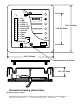
This section of this document describes the keypad interface. The keypad has twelve keys, four rows by three
columns. The characters 0 to 9, # and * are arranged the same as a standard telephone keypad. There are two
methods for interfacing to the Keypad.
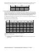
The first configuration (K version, internal keypad) processes the keypad entries in the reader and then
transmits the data to the host system via the Wiegand data lines. The reader outputs each key as an ASCII
encoded hexadecimal digit. The decoding of the message sent through the Wiegand interface is the only