
User's Manual


__________________________________________________________________________________________________________
HID Corporation, 9292 Jeronimo Road, Irvine, CA 92618-1905, USA •Tel: (949) 598-1600, (800) 237-7769, Fax: (949) 598-1690
http://www.hidcorp.com MaxiProx Reader Installation Manual 5375-900 REV 06
Page
2
Chapter 2 Installation Procedure
2.1
2.1 2.1
2.1 Preparation
PreparationPreparation
Preparation
Determine an appropriate mounting position for the MaxiProx. Install an electrical box or drill the
appropriate mounting holes from inside the base with the cover removed for #6 fasteners. For optimum
performance, the Reader should be mounted at least 4 inches away from any metallic surface 12-inch x 12-
inch or larger. The Autotune feature automatically compensates for incidental metal such as aluminum studs
and conduit. The best method for installing the MaxiProx is by mounting the back of the Reader to the
mounting surface. Side mounting is usually accomplished with an adapter or spacer (customer supplied) that
mounts to the back of the Reader.
2.2
2.2 2.2
2.2 Mounting and Installation
Mounting and InstallationMounting and Installation
Mounting and Installation
When fastening the MaxiProx to the mounting surface, do not use a metallic fastener larger than a #6
screw.
Avoid mounting the MaxiProx closer than 1 meter (40-inches) to another MaxiProx.
2.3
2.3 2.3
2.3 Mounting Applications
Mounting ApplicationsMounting Applications
Mounting Applications
The MaxiProx may be mounted to a gooseneck that is 1½-inch in diameter with a 4-inch diameter-
mounting flange without degradation of read range. The flange should be mounted to a non-metallic
adapter that will ease the installation of the MaxiProx to the flange. The read range will not be affected.
The MaxiProx may be mounted to a 12-inch x 12-inch or larger metal plate with a 4-inch spacer used to
separate the Reader from the plate.
Acrylic, Plexiglas, Lexan (polycarbonate) or other suitable plastics may be found in ½-inch to 1-inch
stock. Mounting adapters may be fabricated from these materials that would be sturdy and not affect the
performance of the MaxiProx. Plastic J-boxes can also be used.
2.4
2.4 2.4
2.4 Cable Preparation
Cable PreparationCable Preparation
Cable Preparation
Prepare the cable by cutting the cable jacket back 2 inches and strip the wires 1/4-inch. Tinning the wires is
not required.
2.5
2.5 2.5
2.5 Install Cable
Install CableInstall Cable
Install Cable
Route the interface cable from the MaxiProx to the Host. Connect the MaxiProx DC power input to the Host
or external power supply. Either +12VDC or +24VDC can be used.
CAUTION!
The shunt jumper P2 is not installed as the factory default for +24VDC operation. If the jumper is in the +12
VDC position and +21 to +28.5 VDC is applied, circuit damage can result.
2.6
2.6 2.6
2.6 Cable Notes
Cable NotesCable Notes
Cable Notes
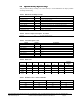
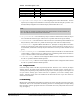
For Wiegand interface cable the maximum length is 500 feet (150m), 50 feet (15m) for RS232, and 4000
feet (1200m) for RS422.
When using 5 conductor cable, the power supply and Host must have a common ground (voltage
reference).