
User's Manual


__________________________________________________________________________________________________________
HID Corporation, 9292 Jeronimo Road, Irvine, CA 92618-1905, USA •Tel: (949) 598-1600, (800) 237-7769, Fax: (949) 598-1690
http://www.hidcorp.com MaxiProx Reader Installation Manual 5375-900 REV 06
Page
6
2.11
2.11 2.11
2.11 Power Supply
Power SupplyPower Supply
Power Supply
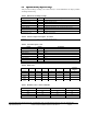
The MaxiProx Reader can be operated over the full range of 11-28.5VDC. Current requirements are 200
mA average and 700 mA peak at 12 VDC input. At 24 VDC (21 to 28.5 VDC) input the average current is
260 mA and peak is 1.2 A. A linear regulated supply rated at 2.0 A is recommended. Noise from devices
such as switching power supplies, computer monitors, and arc welders can reduce the read range or make the
unit inoperable. Keep these devices at least 10 ft away from the Reader. With the MaxiProx and power
supply wired together, apply power to the Reader.
CAUTION!
The shunt jumper P2 is not installed as the factory default for +24VDC operation. If the jumper is in the +12
VDC position and +21 to +28.5 VDC is applied, circuit damage can result.
2.12
2.12 2.12
2.12 Autotune Operation
Autotune OperationAutotune Operation
Autotune Operation
The MaxiProx is tuned correctly when the autotune LED is green. If the LED is red, use a spacer to
position the Reader at minimum of 4 inches away from metal in the mounting surface.
2.13
2.13 2.13
2.13 Reader Testing
Reader Testing Reader Testing
Reader Testing
Apply Power to the Reader and the LED will display a sequence of flashes and beeps, indicating the LED
control mode. Two flashes of green and two beeps followed by a short delay, then one additional flash
(beep), is the correct sequence for "Green Flash/Beep on valid read” (SW1-5 off). Three initial green flashes
and beeps followed by a pause and then one additional beep indicate no Green Flash/Beep on valid read
(SW1-5 on).
2.14
2.14 2.14
2.14 Power-Up Tune
Power-Up TunePower-Up Tune
Power-Up Tune
Following this initial power up sequence the Reader will perform power-up Autotune. It will beep and turn
the access LED amber for ~1 second to indicate that a power-up tune test is about to begin. It will then
attempt to tune. If it successfully tunes, it will give two quick beeps and a
green on the access and tune
LED's to indicate the Reader is tuned. If unsuccessful, the unit will give a single 1.5-second beep with a
red
on the access and tune LED’s. If Autotune is not successful, the installer should check for large areas of
metal less than 4 inches from the back of the unit.
2.15
2.15 2.15
2.15 Periodic Autotune
Periodic AutotunePeriodic Autotune
Periodic Autotune
Periodic Autotune retunes every 1 minute.
2.16
2.16 2.16
2.16 Supervisor Mode
Supervisor ModeSupervisor Mode
Supervisor Mode
During idle periods in normal operation, a periodic supervisor 1 byte transmission is sent to the host
controller over the Wiegand interface every 1 minute. Supervisor Mode is only available in Wiegand
Interface Mode.
2.17
2.17 2.17
2.17 Install Cover
Install CoverInstall Cover
Install Cover
Replace the top cover and top cover screw. Make sure that the autotune indicator LED remains in a steady
green state. If the LED is red, remove the cover and re-mount the unit using a non-metallic spacer to position
it further away from the mounting surface. Reinstall the cover, verify autotune, and install the front label over
the top cover screw and the autotune indicator lens.