
User's Manual


_________________________________________________________________________________________________
HID Corporation 9292 Jeronimo Road Irvine, CA 92618-1905 USA TEL (949)598-1600 (800)237-7769
FAX (949)598-1690 Internet - www.hidcorp.com - HID Mifare Reader Installation Manual 6055-914 Rev A.0 Page 2 of 4
1 Parts List
PARTS LIST (Included) Quantity
- HID MIFARE Reader with snap-on
cover and 18in.
1
- #6-32 x 1” self-tapping panhead
screw
2
- Installation manual 1
PARTS LIST (Not-Included) Quantity
- Wire splice 9
- DC Power supply 12 VDC 1
2 Mounting Instructions
Determine an appropriate mounting location. The
reader may be mounted to any surface, including
metal.
Drill two (2) 3/32-inch (2.5mm) holes
approximately 1 inch deep for mounting the
reader.
Drill a 5/8-inch (16mm) hole for the cable.
A single-gang (2S) electrical junction box may
also be used; reader fits US hole pattern, and the
6-32 screws work with the J-box.
Remove the snap-on cover from the reader and
secure the reader to the mounting surface.
Route the cable from the reader and/or power
supply to the host. A linear type power supply is
recommended. Check all electrical codes for
proper cable installation.
For the cable connection to the panel - use Alpha
#1299C or equivalent.
Test the operation of the reader (Section 4). After
completion of the test, replace the snap-on cover.
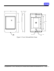
See Figure 1 for product and mounting
dimensions.
For proper regulatory compliance, the drain wire
should be disconnected at the power supply end
of the cable.
Changes or modifications not expressly approved
by the party responsible for compliance could
void the user’s authority to operate the
equipment.
The Reader is intended to be powered from a
limited power source output of a previously
certified power supply.
3 Connecting the Reader
Connect the reader to the host according to the
wiring table below and the host installation guide.
Signal Color DB9F DB25F
9-14 VDC Red - -
GND Black Pin 5 Pin 7
D0 Green - -
D1 White - -
GRN LED Orange - -
RED LED Brown - -
Beeper
HOLD
DSR
RX
DTR
TX
SHLD GND
Yellow
Blue
Violet
Pink
Gray
Tan
Drain
-
Pin 1
-
Pin 2
Pin 4
Pin 3
-
-
Pin 8
-
Pin 3
Pin 20
Pin 2
-
4 Testing and Operation
When power is applied to the reader the beeper
will beep and flash the LED green three times.
Present an ID card to the reader. The LED will
momentarily turn green while the beeper beeps
once, indicating that the card was read
successfully.
Please note that typical read range for MIFARE
cards is .75 to 1.5” (20 – 37 mm).
Important Product Specifications
Power supply
Absolute Maximum Voltage
Maximum Current at 12V
Operating Voltage Range
Linear type
16 VDC
94mA
9.0 – 14.0 VDC
Maximum cable distance
To host
50 ft RS-232
500 ft Wiegand
Operating temperature range
-30 to 65C
FCC Compliance Statement: This device complies
with part 15 of the FCC rules. Operation is subject to
the following two conditions: (1) this device may not
cause harmful interference, and (2) this device must
accept any interference received, including
interference that may cause undesired operation.