
User's Manual

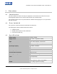

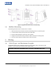

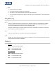

Table Of Contents

6075-900, B.2 – FlexSmart™ 607X Series Installation Guide
The following are recommended cable types and maximum cable lengths for a cable connecting the power supply
to the reader.
Cable Type Maximum Cable Length
24 AWG (0.60mm), three conductors, with an overall foil shield, 9533 or
equivalent.
200’ (61 m)
22 AWG (0.80mm), two conductors, with an overall foil shield, Alpha 5192
or equivalent.
300’ (91 m)
18 AWG (1.20mm), two conductors, with an overall foil shield, 5836 or
equivalent.
500’ (152 m)
The following are recommended wiring types at various maximum distances. Variations in distances
require different wire gauges, because of system data termination differences. Contact your system
manufacturer for its exact requirements. Installation should be in accordance with National Electric Code
ANSI/NFPA 70.
Cable Type Maximum Cable Length
22 AWG (0.80mm), six or eight conductor, with an overall foil shield, Alpha
5196, 5198 or equivalent.
500’(152 m)
18 AWG (1.20mm), six or eight conductor, with an overall foil shield, Alpha
5386, 5388 or equivalent.
500’ (152m)
3.2 Grounding
Connect the reader directly to an earth ground (an earth ground can be established by driving a copper
clad ground rod into the earth). Make certain the DC resistance between your established earth ground
and the system ground is 50 Ohms or less. If a direct connection to a ground rod is not possible, connect
the reader to an earth grounded cold water metal pipe (do not connect to a copper fire sprinkler system
because it may have non-conductive couplings) or steel frames (building beams) that connect to earth.
Connection of the shield/drain to an earth ground will provide greater ESD protection of the reader.
Prevent ground loops by connecting both the cable shield and the negative line of the power supply to one
common earth ground point. Connecting different points to separate earth grounds may result in a ground
loop.
Note: For the heavy duty keypad readers, the Shield/drain wire should be floating at the power supply.
Note: Ground loops may cause poor read range and communication line interference, resulting in no code
or improper code seen by the controller.
Reader Defaults
Reader Wiring
Card read (LED, beep & backlight) Red +12Vdc
One-line control (bi-colour LED) Black 0Vdc
Keypad Defaults Green Data 0/Strobe
Key-press (LED, beep & backlight) White Data 1/Data
1 0001 2 0010 3 0011 Brown LED Control
4 0100 5 0101 6 0110 Blue Beeper Control
7 0111 8 1000 9 1001 Orange Not Used
Θ1010
0 0000 # 1011 Shield/drain Door controller earth ground
Page 6 of 8 February 5, 2007
© 2007 HID Global Corporation. All rights reserved.