BEDIENUNGSANLEITUNG / OWNER’S MANUAL S E R I E Vers. 1.
DE | INHALTSVERZEICHNIS SICHERHEITSHINWEISE 3 INSTALLATIONSHINWEISE 4 MERCURY II 6 Funktionen und Bedienelemente 6 Anschlussbeispiel 2-Kanal-Modus: 1 x Stereo System (Front oder Heck) 7 Anschlussbeispiel 1-Kanal-Modus: 1 x Mono Subwoofer gebrückt 8 MERCURY IV 10 Funktionen und Bedienelemente 10 Anschlussbeispiel 4-Kanal-Modus: 1 Stereo System (Front) und 1 x Stereo System (Heck) 11 Anschlussbeispiel 2-Kanal-Modus: 2 x Mono Subwoofer gebrückt 12 Anschlussbeispiel 3-Kanal-Modus: Stereo Sys
SICHERHEITSHINWEISE|DE BITTE BEACHTEN SIE DIE FOLGENDEN HINWEISE VOR INBETRIEBNAHME! DAS GERÄT NICHT AN STELLEN EINBAUEN, AN DENEN ES HOHER FEUCHTIGKEIT ODER STAUB AUSGESETZT IST. Bauen Sie das Gerät so ein, dass es vor hoher Feuchtigkeit und Staub geschützt ist. Wenn Feuchtigkeit oder Staub in das Gerät gelangen, kann es zu Betriebsstörungen kommen. Schäden am Gerät, welche durch Feuchtigkeit hervorgerufen wurden, unterliegen nicht der Garantie.
DE | INSTALLATIONSHINWEISE HINWEIS! Bevor Sie mit der Installation des Soundsystems beginnen, trennen Sie unbedingt den Massepol der Fahrzeugbatterie ab, um Kurzschlüsse und Stromschläge zu vermeiden. MECHANISCHE INSTALLATION Achten Sie bei der Installation darauf, dass keine serienmäßig im KFZ vorhandenen Teile wie z.B. Kabel, Bordcomputer, Sicherheitsgurte, Tank oder ähnliche Teile beschädigt bzw.entfernt werden. Vergewissern Sie sich, dass der Verstärker am Montageort genügend Kühlung erhält.
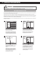
INSTALLATIONSHINWEISE|DE ELEKTRISCHE ANSCHLÜSSE 1 2 3 4 VOR DEM ANSCHLIESSEN Für den fachgerechten Anschluss des Soundsystems sind geeignete Kabelsets im Fachhandel erhältlich. Achten Sie beim Kauf auf einen ausreichenden Kabelquerschnitt (mind. 16 qmm), den passenden Sicherungswert sowie auf die Leitfähigkeit der Kabel. Säubern und entfernen Sie vorhandene Rost- und Oxidationsstellen an allen Kontaktpunkten der Batterie und an den Massepunkten.
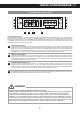
DE | MERCURY II FUNKTIONEN UND BEDIENELEMENTE 1 2 3 4 5 6 7 8 9 1 Die LINE OUT-Cinchausgänge liefern ein lineares Vollbereichs-Audiosignal für die Ansteuerung weiterer Verstärker. 2 Die LINE IN-Cincheingänge sind zur Ansteuerung mittels Cinch-Kabel mit dem Steuergerät zu verbinden. 3 Der HPF-Regler (Hochpassfilter) bestimmt die Begrenzung des Frequenzgangs der Lautsprecher nach unten. Die Trennfrequenz ist stufenlos von 10Hz bis 1200Hz (1.2kHz) regelbar.
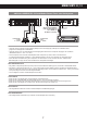
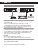
MERCURY II| DE ANSCHLUSSBEISPIEL: 2-Kanal-Modus Stereo Front- oder Hecksystem Stereo Cinch-Audiokabel (L/R) vom Steuergerät mit dem LINE IN des Verstärkers verbinden Schalterstellung: HPF oder FULL R Lautsprecher rechts 2 – 8 Ohm L Lautsprecher links 2 – 8 Ohm VERKABELUNG • Verbinden Sie die Ausgänge des Steuergerätes (Radio) mit den Cinch-Eingängen (LINE IN) des Verstärkers mittels • geeigneten hochwertigen Cinch-Audiokabeln.
DE | MERCURY II ANSCHLUSSBEISPIEL: 1-Kanal-Modus Mono Subwoofer gebrückt Stereo Cinch-Audiokabel (R/L oder SUB OUT) vom Steuergerät mit dem LINE IN R/L verbinden Schalterstellung: LPF/BPF R Subwoofer 4 – 8 Ohm L Bass-Fernbedienung mittels beiliegendem Kabel mit dem Anschluss am Verstärker verbinden VERKABELUNG • Verbinden Sie die Ausgänge des Steuergerätes (Radio) mit den Cinch-Eingängen (LINE IN) des Verstärkers mittels geeigneten hochwertigen Cinch-Audiokabeln.
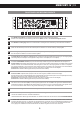
MERCURY IV | DE FUNKTIONEN UND BEDIENELEMENTE 1 2 3 4 5 6 7 8 9 10 11 1 Die LINE IN-Cincheingänge zur Ansteuerung mittels Cinch-Kabel mit dem Steuergerät verbinden. Werden nur die Kanäle CH1 und CH2 belegt, sollte sich der INPUT-Schalter in der Schalterstellung 2CH befinden. 2 Die LINE OUT-Cinchausgänge liefern ein summiertes Mono-Audiosignal für die Ansteuerung eines Subwoofer-Verstärkers. 3 Die HPF-Regler (Hochpassfilter) unter CH1/2 bzw.
DE | MERCURY IV ANSCHLUSSBEISPIEL: 4-Kanal-Modus Stereo Front- und Hecksystem Lautsprecher hinten / links 2 – 8 Ohm Lautsprecher hinten / rechts 2 – 8 Ohm Stereo Cinch-Audiokabel (FL/FR & RL/RR) vom Steuergerät mit LINE INPUT CH1 / CH2 und CH3 / CH4 des Verstärkers verbinden Schalterstellung CH1/2: HPF oder FULL Schalterstellung CH3/4: HPF oder FULL Schalterstellung INPUT: 4 CH FR Lautsprecher vorne / links 2 – 8 Ohm FL RL RR Lautsprecher vorne / rechts 2 – 8 Ohm VERKABELUNG • Verbinden Sie die Ausg
MERCURY IV | DE ANSCHLUSSBEISPIEL: 2-Kanal-Modus Mono 2 Subwoofer gebrückt Subwoofer 2 4 – 8 Ohm Stereo Cinch-Audiokabel (L/R oder SUB OUT) vom Steuergerät mit dem LINE IN CH3/4 verbinden Schalterstellung CH1/2: DUPE Schalterstellung CH3/4: LPF/BPF Schalterstellung INPUT: 4 CH R L Bass-Fernbedienung mittels beiliegendem Kabel mit dem Anschluss am Verstärker verbinden Subwoofer 1 4 – 8 Ohm VERKABELUNG • Verbinden Sie die Ausgänge des Steuergerätes (Radio) mit den Cinch-Eingängen (LINE IN CH 3 und CH 4)
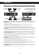
DE | MERCURY IV ANSCHLUSSBEISPIEL: 3-Kanal-Modus Stereo System & Mono Subwoofer gebrückt Stereo Cinch-Audiokabel (FL/FR & RL/RR) vom Steuergerät mit LINE IN CH1 / CH2 und CH3 / CH4 des Verstärkers verbinden Subwoofer 4 – 8 Ohm Schalterstellung CH1/2: HPF oder FULL Schalterstellung CH3/4: LPF/BPF Schalterstellung INPUT: 4 CH FR Lautsprecher vorne / links 2 – 8 Ohm FL RL RR Lautsprecher vorne / rechts 2 – 8 Ohm Bass-Fernbedienung mittels beiliegendem Kabel mit dem Anschluss am Verstärker verbinden VER
TECHNISCHE DATEN| DE MODELLE MERCURY II MERCURY IV KANÄLE SCHALTUNGSPRINZIP 2 CLASS A/B Analog 4 CLASS A/B Analog AUSGANGSLEISTUNG RMS 13,8 V Watt @ 4 Ohm Watt @ 2 Ohm Watt @ 4 Ohm mono gebrückt 2 x 100 2 x 175 1 x 350 4 x 75 4 x 125 2 x 250 AUSGANGSLEISTUNG MAX.
DE | FEHLERBEHEBUNG Fehler: keine Funktion Ursache: Lösung: 1. Die Stromversorgungskabel sind nicht korrekt angeschlossen. Erneute Überprüfung 2. Die Kabel haben keinen elektrischen und mechanischen Kontakt. Erneute Überprüfung 3. Die Remote-Steuerleitung des Steuergeräts (Autoradio) ist nicht korrekt am Verstärker angeschlossen. Erneute Überprüfung 4. Sicherungen defekt. Im Falle des Austauschs achten Sie bitte auf den korrekten Wert der Sicherungen.
FEHLERBEHEBUNG|DE HINWEIS! SCHUTZ-SCHALTUNG Im Verstärker sind verschiedene elektronische Schutzsicherungen integriert. Bei Überlastung, Überhitzung, Kurzschluss an den Lautsprechern, aber auch bei zu niederohmigen Betrieb oder mangelhafter Stromversorgung schaltet dieser ab, um größeren Schäden vorzubeugen. Liegt eine der oben genannten Störungen vor, leuchtet die PROTECT LED (rot) auf. Prüfen Sie in diesem Fall alle Anschlüsse auf Fehler, wie. z.B. Kurzschlüsse, fehlerhafte Verbindungen oder Überhitzung.
TABLE OF CONTENT|ENG SAFETY INSTRUCTIONS 19 INSTALLATION INSTRUCTIONS 20 MERCURY II 21 Features and operational controls 21 Interconnetion example 2-Channel-Mode: 1 x Stereo System (Front or Rear) 22 Interconnetion example 1-Channel-Mode: 1 x Mono Subwoofer bridged 23 MERCURY IV 24 Features and operational controls 24 Interconnetion example 4-Channel-Mode: 1 x Stereo System (Front) and 1 x Stereo System (Rear) 25 Interconnetion example 2-Channel-Mode: 2 x Mono Subwoofer bridged 26 Interc
ENG| SAFETY INSTRUCTIONS PLEASE CHECK THE FOLLOWING ADVICES BEFORE THE FIRST OPERATION! DO NOT INSTALL THE DEVICE AT LOCATIONS, WHERE IT WILL BE EXPOSED TO HIGH HUMIDITY AND DUST. Install the device at a location, where it will be protected from high humidity and dust. If humidity and dust attain inside the device, malfunctions may be caused. THE PURCHASED DEVICE IS ONLY SUITABLE FOR AN OPERATION WITH A 12V ON-BOARD ELECTRICAL SYSTEM OF A VEHICLE.
INSTALLATION INSTRUCTIONS | ENG REFERENCE NOTE Before you start with the installation of the sound system, disconnect by any means the GROUND connection wire from the battery, to avoid any risk of electric shock and short circuits. MECHANICAL INSTALLATION Avoid any damage removing of the components of the vehicle like wires, cables, board computer, seat belts, gastank or the like. Ensure that chosen location provide sufficient air circulation for the amplifier.
ENG| INSTALLATION INSTRUCTIONS ELECTRICAL INTERCONNECTION 1 2 3 4 BEFORE THE CONNECTION For the professional installation of a sound system appropriate wiring kits are available in car audio retailer stores. Attend the sufficient profile section (at least 16 mm2), the suitable fuse rating and the conductivity of the cables when you purchase your wiring kit. Clean and remove rust-streaked and oxidized areas on the contact points of the battery and the ground connection.
MERCURY II|ENG FUNCTIONS AND OPERATIONAL CONTROLS 1 2 3 4 5 6 7 8 9 1 The LINE OUT RCA jacks provide a linear fullrange audiosignal to supply an additional amplifier. 2 The LINE IN RCA jacks must be connected with the RCA output jacks of the headunit. 3 The HPF controller (HIGH PASS) adjusts the cut-off point of the frequency range to below. The cut-off frequency is continuously adjustable from 10 Hz to 1200 Hz (1.2 kHz).
ENG| MERCURY II INTERCONNECTION EXAMPLE 2-Channel Mode: 1x Stereo System (Front or rear) Connect stereo RCA output (L/R) of the headunit with LINE IN of the amplifier Switch position: HPF or FULL R Loudspeaker left 2 – 8 Ohms L Loudspeaker right 2 – 8 Ohms INTERCONNECTION • Connect the RCA lineouts of the headunit with the RCA jacks LINE IN of the amplifier with appropriate high-value RCA cables.
MERCURY II|ENG INTERCONNECTION EXAMPLE 1-Channel Mode: 1x Mono Subwoofer bridged Connect stereo RCA output (L/R or SUB OUT) of the headunit with LINE IN of the amplifier Switch setting: LPF/BPF R Subwoofer 4 – 8 Ohms L Connect the bass level controller on the amplifier with the enclosed cable. INTERCONNECTION • Connect the RCA lineouts of the headunit with the RCA jacks LINE IN of the amplifier with appropriate high-value RCA cables.
ENG| MERCURY IV FUNCTIONS AND OPERATIONAL CONTROLS 1 2 3 4 5 6 7 8 9 10 11 1 The LINE IN RCA jacks must be connected with the RCA output jacks of the headunit. By connecting only the CH1/2 jacks, the INPUT switch must be set to the 2CH position. 2 The LINE OUT RCA jacks provide a summed mono audiosignal to supply an additional subwoofer amplifier. 3 The HPF controller (HIGHPASS) of CH1/2 and CH3/4 adjusts the cut-off point of the frequency range to below for each channelpair.
MERCURY IV|ENG INTERCONNECTION EXAMPLE 4-Channel Mode: 2 x Stereo System (Front & rear) Loudspeaker rear / left 2 – 8 Ohms Loudspeaker rear / right 2 – 8 Ohms Connect the stereo RCA output (FL/FR & RL/RR) of the headunit with LINE IN CH1/2 and CH3/4 of the amplifier Switch setting CH1/2: HPF or FULL Switch setting CH3/4: HPF or FULL Switch setting INPUT: 4 CH FR Loudspeaker front / left 2 – 8 Ohms FL RL RR Loudspeaker front / right 2 – 8 Ohms INTERCONNECTION • Connect the RCA lineouts of the headuni
ENG| MERCURY IV INTERCONNECTION EXAMPLE 2-Channel Mode: 2 x Mono Subwoofer bridged Subwoofer 2 4 – 8 Ohms Connect Stereo RCA output (L/R or SUB OUT) of the headunit with the LINE IN CH1/2 of the amplifier Switch setting CH1/2: DUPE Switch setting CH3/4: LPF/BPF Switch setting INPUT: 4 CH R L Connect the bass level controller on the amplifier with the enclosed cable.
MERCURY IV|ENG EXAMPLE 3-Channel Mode: 1 x Stereo System & 1 x Mono Subwoofer bridged Connect the Stereo RCA outputs (FL/FR & RL/RR) of the headunit withthe LINE IN CH1 / CH2 and CH3 / CH4 of the amplifier Subwoofer 4 – 8 Ohms Switch setting CH1/2: HPF oder FULL Switch setting CH3/4: LPF/BPF Switch setting INPUT: 4 CH FR Speaker left 2 – 8 Ohms FL RL RR Speaker right 2 – 8 Ohms Connect the bass level controller on the amplifier with the enclosed cable.
ENG|SPECIFICATIONS MODELS MERCURY II MERCURY IV CHANNELS CIRCUIT 2 CLASS A/B Analog 4 CLASS A/B Analog OUTPUT POWER RMS 13,8 V Watts @ 4 Ohms Watts @ 2 Ohms Watts @ 4 Ohms mono bridged 2 x 100 2 x 175 1 x 350 4 x 75 4 x 125 2 x 250 OUTPUT POWER MAX.
TROUBLE SHOOTING|ENG Malfunction: no function Reason: Remedy: 1. The power supply connection of the device is not correct. Recheck 2. The cabels have no mechanical or electrical contact. Recheck 3. The remote turn-on connection from the headunit to the amplifier is not correct. Recheck 4. Defective Fuses. In case of replacing the fuses, attend by any means the correct fuse rating. Replace Fuses Malfunction: no signal on loudspeakers, but power LED lights up Reason: Remedy: 1.
ENG|TROUBLE SHOOTING REFERENCE NOTE PROTECTION CIRCUIT This amplifier owns a protection circuit. If overloading, overheating and shorted loudspeakers, or too low impedance or insufficient power supply is insisted, the amplifier shuts down to prevent serious damage. If one of this disfunctions is detected, the red PROTECT LED lights up. Check in this case all connections to detect short-circuits, faulty connections or overheating. Attend the regarding notes on the previous page.
Audio Design GmbH · www.hifonics.de Am Breilingsweg 3 · D-76709 Kronau (Germany) Tel. +49 (0)7253 - 9465-0 · Fax +49 (0)7253 - 946510 Designed and engineered by Audio Design in Germany. All Rights Reserved.