BEDIENUNGSANLEITUNG USER’S MANUAL DIGITAL CLASS D 4-CHANNEL AMPLIFIER PLUTO IV
DEUTSCH SICHERHEITSHINWEISE DAS VON IHNEN ERWORBENE GERÄT IST NUR FÜR DEN BETRIEB AN EINEM 12-V-BORDNETZ EINES FAHRZEUGS AUSGELEGT. Andernfalls besteht Feuergefahr, die Gefahr eines elektrischen Schlages oder anderer Verletzungen. BITTE KEINE BEDIENUNG DES SOUNDSYSTEMS AUSFÜHREN, WELCHE VOM SICHEREN LENKEN DES FAHRZEUGS ABLENKEN KÖNNTE. Führen Sie keine Bedienungen aus, die Ihre Aufmerksamkeit längere Zeit in Anspruch nehmen.
DEUTSCH BEIM BOHREN VON LÖCHERN, BESTEHENDE KOMPONENTEN, LEITUNGEN UND KABEL DES FAHRZEUGS NICHT BESCHÄDIGEN. Wenn Sie bei der Installation Löcher in das Fahrzeugchassis bohren, achten Sie unbedingt darauf die Kraftstoffleitungen, den Benzintank, elektrische Kabel und andere Leitungen nicht zu beschädigen, zu berühren oder zu blockieren. AUF KORREKTE ANSCHLÜSSE ACHTEN. Bei fehlerhaften Anschlüssen besteht Feuergefahr, Kurzschlussgefahr und es kann zu Schäden am Gerät kommen.
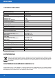
DEUTSCH TECHNISCHE DATEN Modellbezeichnung PLUTO IV Kanäle 4 Schaltung Digital Class D AUSGANGSLEISTUNG RMS @ 14,4 V Watt @ 4 Ohm Watt @ 2 Ohm Watt @ 4 Ohm gebrückt 4 x 50 4 x 95 2 x 190 Lautsprecherimpedanz 2 - 8 Ohm Frequenzgang –3dB 9 - 44000 Hz Dämpfungsfaktor > 100 Signal-Rauschabstand 105 dB Klirrfaktor @ 1W/RMS < 0,005 % Eingangsempfindlichkeit 6 - 0,15 V Filter Front Frequenzweichenmodus Hochpassfilter oder Tiefpassfilter Bass Boost HPF / FULL / LPF 40 - 250 Hz 0 dB / 6 dB / 12
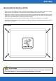
DEUTSCH MECHANISCHE INSTALLATION • Achten Sie bei der Installation darauf, dass keine serienmäßig im KFZ vorhandenen Teile wie z.B. Kabel, Bordcomputer, Sicherheitsgurte, Tank oder ähnliche Teile beschädigt bzw.entfernt werden. • Vergewissern Sie sich, dass der Verstärker am Montageort genügend Kühlung erhält. Montieren Sie das Gerät nicht in zu kleine abgeschlossene Gehäuse ohne Luftzirkulation oder in der Nähe von wärmeabstrahlenden Teilen oder elektronischen Steuerungen des Fahrzeugs.
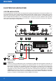
DEUTSCH ELEKTRISCHE ANSCHLÜSSE VOR DEM ANSCHLIESSEN Für den fachgerechten Anschluss des Soundsystems sind geeignete Kabelsets im Fachhandel erhältlich. Achten Sie beim Kauf auf einen ausreichenden Kabelquerschnitt (siehe Tabelle auf der nächsten Seite) und den passenden Sicherungswert der Kabel. Säubern und entfernen Sie vorhandene Rost- und Oxidationsstellen an allen Kontaktpunkten der Batterie und an den Massepunkten.
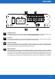
DEUTSCH 2 GERÄTESICHERUNG Steckplatz für die Gerätesicherung (30 A). 3 ZUSÄTZLICHE KABELSICHERUNG (NICHT IM LIEFERUMFANG ENTHALTEN) Installieren Sie eine zusätzliche Sicherung für das Stromkabel in der Nähe der Batterie. Der Abstand zwischen Sicherung und Batterie sollte nicht mehr als 30 cm betragen. Die Sicherungsgröße muss dem Kabelquerschnitt des verlegten Stromkabels angepasst sein (siehe Tabelle unten).
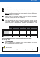
DEUTSCH FUNKTIONSBESCHREIBUNG 7 8 12 13 REM IN REM OUT 8 7 R– L– FL– FR– RL– RR– R+ L+ FL+ FR+ RL+ RR+ REM OUTPUT LOW LEVEL INPUT FRONT REAR HPF FULL LPF 12dB 6dB 0dB 9 10 2CH 4CH 11 12dB 6dB 0dB HPF FULL LPF 10 9 7 FREQ. Diese Regler bestimmen die Trennfrequenz des Hoch- oder Tiefpassfilter am jeweiligen Kanalpaar. Die Trennfrequenz ist von 40 Hz bis 250 Hz stufenlos regelbar. Siehe dazu Abschnitt 9.
DEUTSCH 14 POWER PROTECT RL– INPUT RL+ INPUT 16 FL– INPUT FL+ INPUT FR– INPUT FR+ INPUT HIGH LEVEL INPUT RR– INPUT RR+ INPUT RR– RR+ RL– RL+ FR– FR+ SPEAKER OUTPUT FL– GND GND FL+ +12V +12V LIMITED POWER INPUT FULL POWER INPUT 15 17 14 POWER/PROTECT Leuchtet diese LED blau, ist der Verstärker betriebsbereit. Leuchtet diese rot, liegt eine Fehlfunktion vor. Beachten Sie dann die Hinweise im Abschnitt FEHLERBEHEBUNG auf Seite 12.
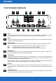
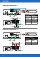
DEUTSCH ANWENDUNGSBEISPIEL A REM REM IN REM OUT R– L– FL– FR– RL– RR– R+ L+ FL+ FR+ RL+ RR+ REM OUTPUT LOW LEVEL INPUT FRONT REAR HPF FULL LPF 12dB 6dB 0dB 2CH 4CH 12dB 6dB 0dB HPF FULL LPF Belegung HPF HPF 4CH od. FULL od.
DEUTSCH ANWENDUNGSBEISPIEL C REM IN REM OUT Belegung R– L– FL– FR– RL– RR– R+ L+ FL+ FR+ RL+ RR+ REM OUTPUT LOW LEVEL INPUT FRONT REAR HPF FULL LPF 12dB 6dB 0dB 2CH 4CH 12dB 6dB 0dB HPF FULL LPF HPF 4CH HPF od. FULL od.
DEUTSCH FEHLERBEHEBUNG ACHTUNG Sämtliche Hinweise dieser Fehlerbehebung beziehen sich auf das gesamte Soundsystem und deren Einzelkomponenten. Unter Umständen entspricht die Ausstattung Ihres Geräts nicht den in den Hinweisen beschriebenen Funktionen. Überspringen Sie dann diesen Punkt und machen mit dem nächsten weiter.
DEUTSCH DIE POWER LED LEUCHTET, ABER ES KOMMT KEIN TON AUS DEN LAUTSPRECHERN Überprüfen Sie folgende Schritte: Niederpegelmodus: Sind die RCA/Cinchkabel am Radio/Steuergerät und am Verstärker korrekt angeschlossen? • Die RCA/Cinchkabel sind korrekt angeschlossen. Es könnte ein RCA/Cinchkabel defekt sein. Überprüfen Sie die Funktion der RCA/Cinchkabel an einem anderen Audiogerät. Ersetzen Sie gegebenenfalls das defekte RCA/Cinchkabel.
DEUTSCH FEHLERBEHEBUNG VERZERRUNGEN ODER ZISCHGERÄUSCHE SIND AUS DEN LAUTSPRECHERN ZU HÖREN Überprüfen Sie folgende Schritte: Ist ein Eingangspegelregler am Verstärker zu hoch eingestellt? Drehen Sie den Regler langsam zurück, bis ein sauberes Audiosignal zu hören. Ist der Bass Boost (Bassanhebung) am Verstärker zu hoch eingestellt? Drehen Sie den Regler langsam zurück, bis ein sauberes Audiosignal zu hören.
DEUTSCH VERSTÄRKER AKTIVIERT DIE SCHUTZSCHALTUNG / DIE PROTECT LED LEUCHTET Überprüfen Sie folgende Schritte: Kurzschluss an den Lautsprecherkabeln • Klemmen Sie zunächst alle Lautsprecherkabel am Verstärker ab. Überprüfen Sie mit einem Multimeter die ohmsche Impedanz jedes Lautsprechers, indem sie zwischen dessen Plus- und Minusleitung messen. Bei handelsüblichen Lautsprechern schwankt der Wert zwischen 3 und 5 Ohm. Die Werte bei niederohmigen Subwoofern können geringer sein.
ENGLISH SAFETY INSTRUCTIONS THE PURCHASED DEVICE IS ONLY SUITABLE FOR AN OPERATION WITH A 12V ON-BOARD ELECTRICAL SYSTEM OF A VEHICLE. Otherwise fire hazard, risk of injury and electric shock consists. PLEASE DO NOT MAKE ANY OPERATION OF THE SOUND SYSTEM, WHICH DISTRACT YOU FROM A SAFE DRIVING. Do not make any procedures, which demand a longer attention. Perform these operations not until you have stopped the vehicle on a safe place. Otherwise the risk of accident consists.
ENGLISH MOUNT THE DEVICE AND OTHER COMPONENTS OF THE SOUND SYSTEM SUFFICIENTLY. Otherwise the device and components may get loose and act as dangerous objects, which could cause serious harm and damages in the passenger room. ENSURE NOT TO DAMAGE COMPONENTS, WIRES AND CABLES OF THE VEHICLE WHEN YOU DRILL THE MOUNTING HOLES.
ENGLISH TECHNICAL SPECIFICATIONS Model PLUTO IV Channels 4 Circuit Digital Class D OUTPUT POWER RMS @ 14.
ENGLISH MECHANICAL INSTALLATION • Avoid any damages on the components of the vehicle like air bags, cables, board computer, seat belts, gas tank or the like. • Ensure that the chosen location provides a sufficient air circulation for the amplifier. Do not mount the device into small sealed spaces without air circulation or near by heat dispersing parts or electrical parts of the vehicle. • All cables must be as short as possible to avoid losses and interferences.
ENGLISH ELECTRICAL INTERCONNECTION BEFORE CONNECTING For the professional installation of a sound system, car audio retail stores offers appropriate wiring kits. Ensure a sufficient profile section (refer to the table on the next page) and a suitable fuse rating and the conductivity of the cables when you purchase your wiring kit. Clean and remove rust-streaked and oxidized areas on the contact points of the battery and the ground connection.
ENGLISH 2 FUSE Slot for the device fuse (30 A). 3 ADDITIONAL CABLE FUSE (NOT INCLUDED) Install an extra fuse (not included) for the +12V power cable near the battery to secure the power cable. The distance between the fuse and the battery should not exceed 30 cm. The fuse size must be adapted to the cable cross-section of the installed power cable (see table below).
ENGLISH DESCRIPTION OF OPERATION 7 8 12 13 REM IN REM OUT 8 7 R– L– FL– FR– RL– RR– R+ L+ FL+ FR+ RL+ RR+ REM OUTPUT LOW LEVEL INPUT FRONT REAR HPF FULL LPF 12dB 6dB 0dB 9 10 2CH 4CH 11 12dB 6dB 0dB HPF FULL LPF 10 9 7 FREQ. These controllers determine the crossover frequency of the high or low pass filter on the respective channel pair. The crossover frequency is adjustable from 40 Hz to 250 Hz (See section 9).
ENGLISH 14 POWER PROTECT RL– INPUT RL+ INPUT 16 FL– INPUT FL+ INPUT FR– INPUT FR+ INPUT HIGH LEVEL INPUT RR– INPUT RR+ INPUT RR– RR+ RL– RL+ FR– FR+ SPEAKER OUTPUT FL– GND GND FL+ +12V +12V LIMITED POWER INPUT FULL POWER INPUT 15 17 14 POWER/PROTECT If the LED lights up in blue, the amplifier is ready for operation. If the LED lights up in red, there is a malfunction. Refer in this case to chapter TROUBLE SHOOTING on page 26.
ENGLISH APPLICATION EXAMPLE A REM REM IN REM OUT R– L– FL– FR– RL– RR– R+ L+ FL+ FR+ RL+ RR+ REM OUTPUT LOW LEVEL INPUT FRONT REAR HPF FULL LPF 12dB 6dB 0dB 2CH HPF or FULL HPF FULL LPF 12dB 6dB 0dB 4CH Assignment HPF or FULL 4CH 0dB 0dB 2-8Ω RL– INPUT RL+ INPUT POWER PROTECT 2-8Ω FL– INPUT FL+ INPUT FR– INPUT FR+ INPUT RR– INPUT RR+ INPUT RR– RR+ RL– RL+ HIGH LEVEL INPUT FR– FR+ FL– GND GND FL+ +12V +12V SPEAKER OUTPUT LIMITED POWER INPUT FULL POWER INPUT Head Unit Amplifier
ENGLISH APPLICATION EXAMPLE C REM IN REM OUT Assignment R– L– FL– FR– RL– RR– R+ L+ FL+ FR+ RL+ RR+ REM OUTPUT LOW LEVEL INPUT FRONT REAR HPF FULL LPF 12dB 6dB 0dB HPF or FULL 2CH 4CH 4CH 0dB HPF FULL LPF 12dB 6dB 0dB HPF or FULL 0dB 2-8Ω POWER PROTECT RL– INPUT RL+ INPUT FL– INPUT FL+ INPUT FR– INPUT FR+ INPUT HIGH LEVEL INPUT RR– INPUT RR+ INPUT RR– RR+ RL– RL+ FR– FR+ SPEAKER OUTPUT Head Unit Amplifier Speaker Outputs High Level Inputs FL FL FR FR RL RL RR RR 2-8Ω
ENGLISH TROUBLE SHOOTING CAUTION All instructions in this trouble shooting refer to the entire sound system and its individual components. The features of your device may not match the functions described in the notes. Then skip this point and move on to the next one. NO FUNCTION / THE POWER LED IS NOT ILLUMINATED First check the fuse of the routed power cable on the vehicle battery The fuse is defective Replace the defective fuse with an equivalent one, never with a higher value. • The fuse fails again.
ENGLISH THE POWER LED IS ON, BUT NO SOUND COMES FROM THE SPEAKERS Check the following steps: Low level mode: Are the RCA cables on the head unit and on the amplifier correctly connected? • The RCA cables are correctly connected. Then an RCA cables could be defective. Check the function of the RCA cables on another audio device. If necessary, replace the defective RCA cables.
ENGLISH TROUBLE SHOOTING DISTORTION OR HISSING NOISE CAN BE HEARD FROM THE SPEAKERS Check the following steps: Is a input level controller on the amplifier set too high? Slowly turn the controller back until you hear a clean audio signal. Is the Bass Boost controller on the amplifier set too high? Slowly turn the controller back until you hear a clean audio signal.
ENGLISH AMPLIFIER ACTIVATES THE PROTECTIVE CIRCUIT / THE PROTECT LED LIGHTS UP Check the following steps: Short circuit on the speaker cables • First disconnect all speaker cables from the amplifier. Use a multimeter to check the ohmic impedance of each loudspeaker by measuring between its plus and minus lines. With standard loudspeakers the value fluctuates between 3 and 5 ohms. The values for low-resistance subwoofers can be lower. • The measurement shows a resistance value of less than 0.
Audio Design GmbH Am Breilingsweg 3 · D-76709 Kronau/Germany Tel. +49 7253 - 9465-0 · Fax +49 7253 - 946510 www.audiodesign.de - www.hifonics.