BEDIENUNGSANLEITUNG / OWNER’S MANUAL S E R I E Vers. 1.
DE | INHALTSVERZEICHNIS SICHERHEITSHINWEISE 3 INSTALLATIONSHINWEISE 4 BETRIEBSHINWEISE 6 Funktionen und Bedienelemente 6 Anschlussbeispiel: Tiefpass-Modus (normaler Subwoofer-Betrieb) 7 Anschlussbeispiel Hochpass/Vollbereich-Modus: 1 Lautsprecher-System und weiterem TRITON I Verstärker 8 TECHNISCHE DATEN & GARANTIEHINWEIS 10 FEHLERBEHEBUNG 11 THE OWNER’S MANUAL IN ENGLISH STARTS ON PAGE 13 Dieses Symbol weist Sie auf wichtige Hinweise auf den folgenden Seiten hin.
SICHERHEITSHINWEISE|DE BITTE BEACHTEN SIE DIE FOLGENDEN HINWEISE VOR INBETRIEBNAHME! DAS VON IHNEN ERWORBENE GERÄT IST NUR FÜR DEN BETRIEB AN EINEM 12-V-BORDNETZ EINES FAHRZEUGS AUSGELEGT. Andernfalls besteht Feuergefahr, die Gefahr eines elektrischen Schlages oder anderer Verletzungen. LAUTSPRECHERKABEL DÜRFEN KEINEN KONTAKT ZUR KAROSSERIE/MASSE HABEN. Andernfalls könnten ernsthafte Schäden an den einzelnen Komponenten und der Fahrzeugelektrik entstehen.
DE | INSTALLATIONSHINWEISE HINWEIS! Bevor Sie mit der Installation des Soundsystems beginnen, trennen Sie unbedingt den Massepol der Fahrzeugbatterie ab, um Kurzschlüsse und Stromschläge zu vermeiden. MECHANISCHE INSTALLATION Achten Sie bei der Installation darauf, dass keine serienmäßig im KFZ vorhandenen Teile wie z.B. Kabel, Bordcomputer, Sicherheitsgurte, Tank oder ähnliche Teile beschädigt bzw.entfernt werden. Vergewissern Sie sich, dass der Verstärker am Montageort genügend Kühlung erhält.
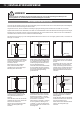
INSTALLATIONSHINWEISE|DE ELEKTRISCHE ANSCHLÜSSE 1 2 3 4 5 VOR DEM ANSCHLIESSEN Für den fachgerechten Anschluss des Soundsystems sind geeignete Kabelsets im Fachhandel erhältlich. Achten Sie beim Kauf auf einen ausreichenden Kabelquerschnitt (mind. 16 qmm), den passenden Sicherungswert sowie auf die Leitfähigkeit der Kabel. Säubern und entfernen Sie vorhandene Rost- und Oxidationsstellen an allen Kontaktpunkten der Batterie und an den Massepunkten.
DE | BETRIEBSHINWEISE FUNKTIONEN UND BEDIENELEMENTE 1 2 3 4 5 6 7 8 9 10 11 1 Der XOVER MODE-Schalter (Frequenzweichenschalter) selektiert die gewünschte Betriebsart: 2 Der BASS LEVEL CONTROLLER-Anschluss dient zum Anschluss des Kabels der im Lieferumfang enthaltenen Bass-Fernbedienung BLC-TR, mit welcher der Bass-Pegel z.B. vom Fahrersitz aus eingestellt werden. Verwenden Sie nur die mitgelieferte Fernbedienung sowie das dazugehörende Kabel. Die Fernbedienung funktioniert nur im LPF/BPF.
BETRIEBSHINWEISE | DE ANSCHLUSSBEISPIEL: Tiefpass-Modus (normaler Subwoofer-Betrieb) Position XOVER MODE: LPF/BPF R Subwoofer 2 – 8 Ohm HINWEIS! L BLC-TR Optional kann noch ein zweiter Subwoofer an die nicht belegten Anschlussklemmen angeschlossen werden. Dann muss die Impedanz pro Subwoofer 4 - 8 Ohm betragen.
DE | BETRIEBSHINWEISE ANSCHLUSSBEISPIEL: Hochpass/Vollbereich-Modus mit 1 Lautsprechersystem HINWEIS! Dieses Anschlussbeispiel ist nur dann sinnvoll, wenn Sie in Kombination mit einem weiteren TRITON I Verstärker ein sehr belastbares Stereo-Lautsprecher-System betreiben möchten. Hierbei übernimmt dann jeweils ein Verstärker im Hochpass- oder Vollbereich-Modus einen Kanal mit bis zu 400 Watt RMS an 2 Ohm.
BETRIEBSHINWEISE | DE ANSCHLUSSBEISPIEL: Hochpass/Vollbereich-Modus mit 1 Lautsprechersystem VERKABELUNG VERSTÄRKER 1 • Verbinden Sie den Ausgang L des Steuergerätes (Radio) mit den Cinch-Eingängen (LINE IN L & R) des Verstärkers mittels • geeigneten hochwertigen Cinch-Audiokabeln und einem Y-Adapter (1F/2M) um das Eingangssignal zu splitten.
DE | TECHNISCHE DATEN MODELL TRITON I Technische Änderungen und Irrtümer vorbehalten! KANÄLE SCHALTUNGSPRINZIP 1 CLASS A/B Analog Für Schäden am Fahrzeug oder Gerätedefekte, hervorgerufen durch Bedienungsfehler des Geräts, können wir keine Haftung übernehmen. AUSGANGSLEISTUNG RMS 13,8 V Watt @ 4 Ohm Watt @ 2 Ohm 1 x 250 1 x 450 Alle HiFonics Verstärker sind mit einer individuellen Seriennummer versehen, die für statistische und servicebedingte Zwecke aufgezeichnet wird. AUSGANGSLEISTUNG MAX.
FEHLERBEHEBUNG |DE Fehler: keine Funktion Ursache: Lösung: 1. Die Stromversorgungskabel sind nicht korrekt angeschlossen. Erneute Überprüfung 2. Die Kabel haben keinen elektrischen und mechanischen Kontakt. Erneute Überprüfung 3. Die Remote-Steuerleitung des Steuergeräts (Autoradio) ist nicht korrekt am Verstärker angeschlossen. Erneute Überprüfung 4. Die Hochpegel-Anschlüsse sind nicht korrekt angeschlossen und AUTO TURN ON ist angeschaltet Beachten Sie S. 5 und S. 10 5.
DE | FEHLERBEHEBUNG HINWEIS! SCHUTZ-SCHALTUNG Im Verstärker sind verschiedene elektronische Schutzsicherungen integriert. Bei Überlastung, Überhitzung, Kurzschluss an den Lautsprechern, aber auch bei zu niederohmigen Betrieb oder mangelhafter Stromversorgung schaltet dieser ab, um größeren Schäden vorzubeugen. Liegt eine der oben genannten Störungen vor, leuchtet die PROTECT LED (rot) auf. Prüfen Sie in diesem Fall alle Anschlüsse auf Fehler, wie. z.B.
TABLE OF CONTENT|ENG SAFETY INSTRUCTIONS 14 INSTALLATION INSTRUCTIONS 15 OPERATIONAL INSTRUCTIONS 17 Features and operational controls 17 Interconnection example: Lowpass-mode (regular subwoofer operation) 18 Interconnection example: Highpass/fullrange-mode: 1 x speaker system with additional TRITON I amplifier 19 SPECIFICATIONS & WARRANTY DISCLAIMER 21 TROUBLE SHOOTING 22 This symbol adverts you a important reference note on the following pages.
ENG| SAFETY INSTRUCTIONS PLEASE CHECK THE FOLLOWING ADVICES BEFORE THE FIRST OPERATION! THE PURCHASED DEVICE IS ONLY SUITABLE FOR AN OPERATION WITH A 12V ON-BOARD ELECTRICAL SYSTEM OF A VEHICLE. Otherwise fire hazard, risk of injury and electric shock consists. ENSURE THAT THE LOUDSPEAKER CABLES HAVE NO CONTACT WITH THE VEHICLE’S CHASSIS/GROUND. Otherwise serious damages on the components and the electrical system may occur.
INSTALLATION INSTRUCTIONS | ENG REFERENCE NOTE Before you start with the installation of the sound system, disconnect by any means the GROUND connection wire from the battery, to avoid any risk of electric shock and short circuits. MECHANICAL INSTALLATION Avoid any damage removing of the components of the vehicle like wires, cables, board computer, seat belts, gastank or the like. Ensure that chosen location provide sufficient air circulation for the amplifier.
ENG| INSTALLATION INSTRUCTIONS ELECTRICAL INTERCONNECTION 1 2 3 4 5 BEFORE THE CONNECTION For the professional installation of a sound system appropriate wiring kits are available in car audio retailer stores. Attend the sufficient profile section (at least 16 mm2), the suitable fuse rating and the conductivity of the cables when you purchase your wiring kit. Clean and remove rust-streaked and oxidized areas on the contact points of the battery and the ground connection.
OPERATIONAL INSTRUCTIONS|ENG FUNCTIONS AND OPERATIONAL CONTROLS 1 2 3 4 5 6 7 8 9 10 11 1 The X-OVER MODE switch selects the required operation mode: 2 The BASS LEVEL CONTROLLER port is for the cable of the enclosed bass remote controller. With this bass remote controller, you are able to adjust the bass level e.g. out of the driver’s seat. Please use only the enclosed bass remote controller and cable. The controller works only in LPF/BPF.
ENG|OPERATIONAL INSTRUCTIONS INTERCONNECTION EXAMPLE LOWPASS-MODE: 1 x Subwoofer Position XOVER MODE: LPF/BPF R Subwoofer 2 – 8 Ohm NOTE! L BLC-TR An additional subwoofer can be connected to the non-occupied speaker outputs. In this case ensure a impedance of 4 - 8 ohms per subwoofer. Connect RCA output (L/R) of the headunit with LINE IN of the amplifier INTERCONNECTION • Connect the RCA lineouts of the headunit with the RCA jacks LINE IN of the amplifier with appropriate high-value RCA cables.
OPERATIONAL INSTRUCTIONS|ENG INTERCONNECTION EXAMPLE HIGHPASS/FULLRANGE: 1 x Speaker System NOTE! This example makes only sense, if you have an additional TRITON I amplifier and you want to run a powerful stereo speaker system. In this case, each amplifier supplies one channel of the speaker system in highpass or fullrange mode with up to 400 watts RMS @ 2 ohms. Position XOVER MODE: HPF or FULL AMPLIFIER 1 NOTE! An additional speaker can be connected to the non-occupied speaker outputs.
ENG|OPERATIONAL INSTRUCTIONS INTERCONNECTION EXAMPLE HIGHPASS/FULLRANGE: 1 x Speaker System INTERCONNECTION AMPLIFIER 1 • Connect the RCA lineout L of the headunit with the RCA jacks LINE IN R & L of the amplifier with appropriate high-value RCA cables and a Y-connector (1F/2M) to split the signal. • Connect the speaker (left) with the speaker outputs (SPEAKER OUTPUTS + and - of the same socket) by using appropriate wires.
SPECIFICATIONS |ENG MODEL TRITON I CHANNELS CIRCUIT 1 CLASS A/B Analog OUTPUT POWER RMS 13,8 V Watts @ 4 Ohms Watts @ 2 Ohms 1 x 250 1 x 450 OUTPUT POWER MAX. 13,8 V Watts @ 4 Ohms Watts @ 2 Ohms 1 x 500 1 x 900 Frequency Range –3dB Damping Factor Signal-to-Noise Ratio THD&N Input Sensitivity Input Impedance 20Hz - 30 kHz > 800 > 90 dB 0,05% 6 - 0.
ENG|TROUBLE SHOOTING Malfunction: no function Reason: Remedy: 1. The power supply connection of the device is not correct. Recheck 2. The cables have no mechanical or electrical contact. Recheck 3. The remote turn-on connection from the headunit to the amplifier is not correct. Recheck 4. The high level inputs (from the head unit) are not connected correct and AUTO TURN ON is activated. See page 16 and 21 5.
TROUBLE SHOOTING|ENG REFERENCE NOTE PROTECTION CIRCUIT This amplifier owns a protection circuit. If overloading, overheating and shorted loudspeakers, or too low impedance or insufficient power supply is insisted, the amplifier shuts down to prevent serious damage. If one of this disfunctions is detected, the red PROTECT LED lights up. Check in this case all connections to detect short-circuits, faulty connections or overheating. Attend the regarding notes on the previous page.
Audio Design GmbH · www.hifonics.de Am Breilingsweg 3 · D-76709 Kronau (Germany) Tel. +49 (0)7253 - 9465-0 · Fax +49 (0)7253 - 946510 Designed and engineered by Audio Design in Germany. All Rights Reserved.