Z3 SERIES REV. VERS. 1.
INHALTSVERZEICHNIS SICHERHEITSHINWEISE 3 INSTALLATIONSHINWEISE 4 ZXi1501 & ZXi2201 6 Funktionen und Bedienelemente 6 Anschlussbeispiel: Tiefpass-Modus mit einem Subwoofer 7 Anschlussbeispiel: Master/Slave-Modus 8 Anschlussbeispiel: Vollbereichs-Modus mit einem Subwoofer 10 EINSTELLBEREICH DER FILTER 11 TECHNISCHE DATEN & GARANTIEHINWEIS 12 FEHLERBEHEBUNG 13 15 OWNER’S MANUAL IN ENGLISH FROM PAGE 15 Dieses Symbol weist Sie auf wichtige Hinweise auf den folgenden Seiten hin.
SICHERHEITSHINWEISE BITTE BEACHTEN SIE DIE FOLGENDEN HINWEISE VOR INBETRIEBNAHME! DAS GERÄT NICHT AN STELLEN EINBAUEN, AN DENEN ES HOHER FEUCHTIGKEIT ODER STAUB AUSGESETZT IST. Bauen Sie das Gerät so ein, dass es vor hoher Feuchtigkeit und Staub geschützt ist. Wenn Feuchtigkeit oder Staub in das Gerät gelangen, kann es zu Betriebsstörungen kommen. Schäden am Gerät, welche durch Feuchtigkeit hervorgerufen wurden, unterliegen nicht der Garantie.
INSTALLATIONSHINWEISE HINWEIS! Bevor Sie mit der Installation des Soundsystems beginnen, trennen Sie unbedingt den Massepol der Fahrzeugbatterie ab, um Kurzschlüsse und Stromschläge zu vermeiden. MECHANISCHE INSTALLATION Achten Sie bei der Installation darauf, dass keine serienmäßig im KFZ vorhandenen Teile wie z.B. Kabel, Bordcomputer, Sicherheitsgurte, Tank oder ähnliche Teile beschädigt bzw.entfernt werden. Vergewissern Sie sich, dass der Verstärker am Montageort genügend Kühlung erhält.
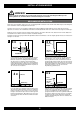
INSTALLATIONSHINWEISE ELEKTRISCHE ANSCHLÜSSE LOGO BADGE GND REM + BATT +12V BLUE WHITE + – FUSE – PROTECT BRIDGE ON OFF SPEAKER OUTPUT POWER INPUT 1 2 3 4 5 6 VOR DEM ANSCHLIESSEN Für den fachgerechten Anschluss des Soundsystems sind geeignete Kabelsets im Fachhandel erhältlich. Achten Sie beim Kauf auf einen ausreichenden Kabelquerschnitt (mind. 25 qmm), den passenden Sicherungswert sowie auf die Leitfähigkeit der Kabel.
ZXi1501 · ZXi2201 FUNKTIONEN UND BEDIENELEMENTE PHASE POWER 0° PROTECT REMOTE FREQ RANGE 180° 20Hz Q-CONTROL 80Hz WIDE SUB BOOST NRW 0dB 18dB MODE SLAVE FULL LP SUB SONIC 15Hz LOW PASS 55Hz 35Hz LEVEL 250Hz 9V 1 2 3 LINE INPUT L L R R 0.2V EXTENDED BASS CONTROL ZXi 2201 1x1100 Watts 1 SLAVE OUTPUT 4 5 6 7 8 9 10 POWER/PROTECT Leuchtet die POWER LED ist der Verstärker betriebsbereit. Leuchtet die PROTECT LED auf, liegt eine Fehlfunktion vor.
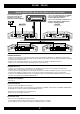
ZXi1501 · ZXi2201 ANSCHLUSSBEISPIEL: Tiefpass-Modus mit einem Subwoofer LOGO BADGE GND REM + BATT +12V BLUE WHITE + – FUSE – PROTECT 0° PROTECT ON OFF POWER INPUT REMOTE FREQ RANGE 180° 20Hz Q-CONTROL 80Hz WIDE SUB BOOST NRW 0dB 18dB MODE SLAVE FULL LP SUB SONIC 15Hz LOW PASS 55Hz 35Hz LEVEL 250Hz 9V SLAVE OUTPUT LINE INPUT L L R R 0.
ZXi1501 · ZXi2201 ANSCHLUSSBEISPIEL: Master/Slave-Modus mit zwei Verstärker Bass-Fernbedienung mittels beiliegendem Kabel mit dem Anschluss am Verstärker (MASTER) verbinden (REMOTE) 1. Stereo Cinch-Audiokabel (R/L od. SUB OUT) vom Steuergerät mit LINE INPUT R/L des Verstärkers (MASTER) verbinden. Steuerleitung REM 2. Stereo Cinch-Audiokabel (SLAVE OUT) vom Verstärkers (MASTER) mit LINE INPUT des Verstärkers (SLAVE) verbinden. 1.
ZXi1501 · ZXi2201 ANSCHLUSSBEISPIEL: Subwoofer mit Single-Schwingspule MASTER/SLAVE Link wie auf Seite 8 beschrieben. MASTER LOGO BADGE GND REM + BATT +12V BLUE WHITE + – – FUSE SLAVE PROTECT LOGO BADGE GND REM + BATT +12V BLUE WHITE BRIDGE ON OFF + – – FUSE PROTECT BRIDGE ON OFF SPEAKER OUTPUT POWER INPUT SPEAKER OUTPUT POWER INPUT Die Impedanz des Subwoofers von 2 Ohm darf nicht unterschritten werden.
ZXi1501 · ZXi2201 ANSCHLUSSBEISPIEL: Vollbereich-Modus mit einem Subwoofer LOGO BADGE GND REM + BATT +12V BLUE WHITE + – FUSE – PROTECT 0° PROTECT ON OFF POWER INPUT PHASE POWER BRIDGE REMOTE FREQ RANGE 180° 20Hz Q-CONTROL 80Hz WIDE SUB BOOST NRW 0dB 18dB MODE SLAVE FULL LP SUB SONIC 15Hz LOW PASS 55Hz 35Hz SLAVE OUTPUT LINE INPUT L L R R 0.
EINSTELLBEREICHE DER FILTER LEVEL 0,7 V 4V 0,25 V 9V 0,2 V SUB SONIC 35 Hz 21 Hz 48 Hz 15 Hz 55 Hz LOW PASS 140 Hz 40 Hz 220 Hz 35 Hz 250 Hz EXTENDED BASS CONTROL SUB BOOST 9 dB 3 dB 15 dB 0 dB 18 dB FREQ RANGE 50 Hz 30 Hz 70 Hz 20 Hz 80 Hz PHASE 90° 30° 150° 0° 180° WIDE Q-CONTROL NARROW 0,5 0,4 0,7 0,3 1,0 Q = 0,3 Q = 1,0 +18dB +12dB +6dB 0dB 20Hz 40Hz 11 60Hz 80Hz
TECHNISCHE DATEN MODELLE ZXi1501 ZXi2201 KANÄLE SCHALTUNGSPRINZIP 1 CLASS IGBT Analog 1 CLASS IGBT Analog AUSGANGSLEISTUNG RMS 13,8 V Watt an 4 Ohm Watt an 2 Ohm Watt an 1 Ohm 1 x 300 1 x 500 1 x 750 1 x 400 1 x 700 1 x 1100 AUSGANGSLEISTUNG MAX. 13,8 V Watt an 4 Ohm Watt an 2 Ohm Watt an 1 Ohm 1 x 600 1 x 1000 1 x 1500 1 x 800 1 x 1400 1 x 2200 Dämpfungsfaktor Signal-Rauschabstand Klirrfaktor (THD&N) Eingangsempfindlichkeit Eingangsimpedanz > 200 > 90 dB < 0,03% 9 - 0.
FEHLERBEHEBUNG Fehler: keine Funktion Ursache: Lösung: 1. Die Stromversorgungskabel sind nicht korrekt angeschlossen. Erneute Überprüfung 2. Die Kabel haben keinen elektrischen und mechanischen Kontakt. Erneute Überprüfung 3. Die Remote-Steuerleitung des Steuergeräts (Autoradio) ist nicht korrekt am Verstärker angeschlossen. Erneute Überprüfung 4. Sicherungen defekt. Im Falle des Austauschs achten Sie bitte auf den korrekten Wert der Sicherungen.
FEHLERBEHEBUNG HINWEIS! SCHUTZ-SCHALTUNG Im Verstärker sind verschiedene elektronische Schutzsicherungen integriert. Bei Überlastung, Überhitzung, Kurzschluss an den Lautsprechern, aber auch bei zu niederohmigen Betrieb oder mangelhafter Stromversorgung schaltet dieser ab, um größeren Schäden vorzubeugen. Liegt eine der oben genannten Störungen vor, leuchtet die PROTECT LED (rot) auf. Prüfen Sie in diesem Fall alle Anschlüsse auf Fehler, wie. z.B. Kurzschlüsse, fehlerhafte Verbindungen oder Überhitzung.
TABLE OF CONTENT SAFETY INSTRUCTIONS 16 INSTALLATION INSTRUCTIONS 17 ZXi1501 & ZXi2201 19 Features and operational controls 19 Interconnetion example Low Pass-Mode with 1 Subwoofer 20 Interconnetion example Master/Slave-Mode 21 Interconnetion example Full Range-Mode with 1 Subwoofer 23 FILTER SETTING RANGE 24 SPECIFICATIONS & WARRANTY DISCLAIMER 25 TROUBLE SHOOTING 26 This symbol adverts you a important reference note on the following pages.
SAFETY INSTRUCTIONS PLEASE ATTEND THE FOLLOWING ADVICES BEFORE THE FIRST OPERATION! THE PURCHASED DEVICE IS ONLY SUITABLE FOR AN OPERATION WITH A 12V ON-BOARD ELECTRICAL SYSTEM OF A VEHICLE. Otherwise fire hazard, risk of injury and electric shock consists. DO NOT INSTALL THE DEVICE AT LOCATIONS, WHERE IT WILL BE EXPOSED TO HIGH HUMIDITY AND DUST. Install the device at a location, where it will be protected from high humidity and dust.
INSTALLATION INSTRUCTION REFERENCE NOTE Before you start with the installation of the sound system, disconnect by any means the GROUND connection wire from the battery, to avoid any risk of electric shock and short circuits. MECHANICAL INSTALLATION Avoid any damage removing of the components of the vehicle like wires, cables, board computer, seat belts, gastank or the like. Ensure that chosen location provide sufficient air circulation for the amplifier.
INSTALLATION INSTRUCTION ELECTRICAL INTERCONNECTION LOGO BADGE GND REM + BATT +12V BLUE WHITE + – – FUSE PROTECT BRIDGE ON OFF SPEAKER OUTPUT POWER INPUT 1 2 3 4 5 6 BEFORE THE CONNECTION For the professional installation of a sound system appropriate wiring kits are available in car audio retailer stores. Attend the sufficient profile section (at least 25 mm2), the suitable fuse rating and the conductivity of the cables when you purchase your wiring kit.
ZXi1501 · ZXi2201 FUNCTIONS AND OPERATIONAL CONTROLS PHASE POWER 0° PROTECT REMOTE FREQ RANGE 180° 20Hz Q-CONTROL 80Hz WIDE SUB BOOST NRW 0dB 18dB SUB SONIC MODE SLAVE FULL LP 15Hz LOW PASS 55Hz 35Hz LEVEL 250Hz 9V 1 2 3 LINE INPUT L L R R 0.2V EXTENDED BASS CONTROL ZXi 2201 1x1100 Watts 1 SLAVE OUTPUT 4 5 6 7 8 9 10 POWER/PROTECT If the POWER LED lights up, the amplifier is ready for operation. If the PROTECT LED lights up, a malfunction is indicated.
ZXi1501 · ZXi2201 INTERCONNECTION EXAMPLE Low-Pass Mode with 1 Subwoofer LOGO BADGE GND REM + BATT +12V BLUE WHITE + – FUSE – PROTECT 0° PROTECT ON OFF POWER INPUT PHASE POWER BRIDGE REMOTE FREQ RANGE 180° 20Hz Q-CONTROL 80Hz WIDE SUB BOOST NRW 0dB 18dB MODE SLAVE FULL LP SUB SONIC 15Hz LOW PASS 55Hz 35Hz SLAVE OUTPUT LINE INPUT L L R R 0.
ZXi1501 · ZXi2201 INTERCONNECTION EXAMPLE Master/Slave Mode Connect the bass remote controller and the remote terminal on the amplifier (MASTER) with the enclosed cable (REMOTE). 1. Connect Stereo RCA output (CH1/2 L/R or SUB OUT) of the headunit with the LINE INPUT CH1/2 of the amplifier (MASTER) Remote wire REM 2. Connect Stereo RCA cable (SLAVE OUT) of the amplfier (MASTER) with the LINE INPUT of the amplifier (SLAVE) 1.
ZXi1501 · ZXi2201 INTERCONNECTION EXAMPLE 1 Subwoofer with a Single-Voicecoil MASTER/SLAVE Link like described on page 22. MASTER LOGO BADGE GND REM + BATT +12V BLUE WHITE + – – FUSE SLAVE PROTECT LOGO BADGE GND REM + BATT +12V BLUE WHITE BRIDGE ON OFF + – – FUSE PROTECT BRIDGE ON OFF SPEAKER OUTPUT POWER INPUT SPEAKER OUTPUT POWER INPUT The Impedance may not be lower than 2 ohms.
ZXi1501 · ZXi2201 INTERCONNECTION EXAMPLE Full Range Mode with 1 Subwoofer LOGO BADGE GND REM + BATT +12V BLUE WHITE + – – FUSE PROTECT 0° PROTECT ON OFF POWER INPUT PHASE POWER BRIDGE REMOTE FREQ RANGE 180° 20Hz Q-CONTROL 80Hz WIDE SUB BOOST NRW 0dB 18dB MODE SLAVE FULL LP SUB SONIC 15Hz LOW PASS 55Hz 35Hz SLAVE OUTPUT LINE INPUT L L R R 0.
FILTER SETTING RANGE LEVEL 0,7 V 4V 0,25 V 9V 0,2 V SUB SONIC 35 Hz 21 Hz 48 Hz 15 Hz 55 Hz LOW PASS 140 Hz 40 Hz 220 Hz 35 Hz 250 Hz EXTENDED BASS CONTROL SUB BOOST 9 dB 3 dB 15 dB 0 dB 18 dB FREQ RANGE 50 Hz 30 Hz 70 Hz 20 Hz 80 Hz PHASE 90° 30° 150° 0° 180° WIDE Q-CONTROL NARROW 0,5 0,4 0,7 0,3 1,0 Q = 0,3 Q = 1,0 +18dB +12dB +6dB 0dB 20Hz 40Hz 24 25 26 60Hz 80Hz
SPECIFICATIONS MODELS ZXi1501 ZXi2201 CHANNELS CIRCUIT 1 CLASS IGBT Analog 1 CLASS IGBT Analog OUTPUT POWER RMS 13,8 V Watts on 4 Ohms Watts on 2 Ohms Watts on 1 Ohms 1 x 300 1 x 500 1 x 750 1 x 400 1 x 700 1 x 1100 OUTPUT POWER MAX. 13,8 V Watts on 4 Ohms Watts on 2 Ohms Watts on 1 Ohms 1 x 600 1 x 1000 1 x 1500 1 x 800 1 x 1400 1 x 2200 Damping Factor Signal-to-Noise Ratio THD&N Input Sensitivity Input Impedance > 200 > 90 dB < 0,03% 9 - 0.2 V > 47 kOhm > 200 > 90 dB < 0,03% 9 - 0.
TROUBLE SHOOTING Malfunction: no function Reason: Remedy: 1. The power supply connection of the device is not correct. Recheck 2. The cabels have no mechanical or electrical contact. Recheck 3. The remote turn-on connection from the headunit to the amplifier is not correct. Recheck 4. Defective Fuses. In case of replacing the fuses, attend by any means the correct fuse rating. Replace Fuses Malfunction: no signal on loudspeakers, but power LED lights up Reason: Remedy: 1.
TROUBLE SHOOTING REFERENCE NOTE PROTECTION CIRCUIT This amplifier owns a protection circuit. If overloading, overheating and shorted loudspeakers, or too low impedance or insufficient power supply is insisted, the amplifier shuts down to prevent serious damage. If one of this disfunctions is detected, the red PROTECT LED lights up. Check in this case all connections to detect short-circuits, faulty connections or overheating. Attend the regarding notes on the previous page.
Audio Design GmbH · www.hifonics.de Am Breilingsweg 3 · D-76709 Kronau (Germany) Tel.