evc/epc Controller With SAE J1939 Interface evc/epc Electronic Valve Controller User Manual High Country Tek, Inc. reserves the right to improve this product at any time and without notice. This manual may contain mistakes and printing errors. The content is regularly checked and updated. Please check our website or contact our customer support for latest version. HCT accepts NO liability for technical mistakes or printing errors or their consequence. 023-00354-Rev1.
evc/epc Controller With SAE J1939 Interface Contents Welcome ................................................................................................................................................................. 3 Warranty Information .............................................................................................................................................. 3 Product Application Guidelines .........................................................................................
evc/epc Controller With SAE J1939 Interface Welcome Welcome to the High Country Tek Inc. HCT is North America’s foremost independent designer and producer of modular, ruggedized digital and analog electronic controllers for the fluid power industry. From our factory in California, we build, test and produce ‘specialty’ controllers for specific functions and user programmable ‘DVC family’ to enable large area networked system solutions. The modules are used in mobile, industrial and marine applications.
evc/epc Controller With SAE J1939 Interface Product Application Guidelines ALWAYS do the following FULLY read this manual and product data sheets BEFORE starting. Isolate the controller from all other equipment BEFORE any form of welding. Isolate the controller from ANY form of battery charging or battery boosting. Be aware of the electrical & mechanical connections, and the expected reactions of the equipment. Operate the controller within the temperature range.
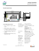
evc/epc Controller With SAE J1939 Interface Controller Specification 125mm 58mm 114mm 48.5mm 7 8 9 10 11 12 6 5 4 3 2 1 CL 2x Ø5 Housing Type HCT encapsulated block Controller Mounting Information Power Supply Voltage 9 to 32VDC (Absolute maximum) Current Consumption Valve current + 50mA Quiescent (Max) Command Inputs SAE J1939 Mount controller in an easily accessible location. Mount controller to a flat, cool surface.
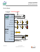
evc/epc Controller With SAE J1939 Interface Electrical Diagram +V Power Input 9 - 32VDC FUSE PWR 1 Enable 8 ENABLE I/P: +V = Enabled Manual Coil Select: +V = Coil B Coil Select 9 Supply Voltage +5VDC @ 250mA Ref.
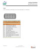
evc/epc Controller With SAE J1939 Interface PINOUT evc/epc controller has a 12-Pin Deutsch connector and a mini-USB port for communication. 023-00354-Rev1.6 evc/epc User Manual Copyright © High Country Tek, Inc.
evc/epc Controller With SAE J1939 Interface LED Diagnostic Codes ( common to both modules ) Module Status LED GREEN steady ------------------------------------------- Normal operation RED 1 pulse ---------------------------------------------- Output A short detected RED 2 pulses --------------------------------------------- Output B short detected GREEN 1 pulse ------------------------------------------ Output A open detected GREEN 2 pulses ----------------------------------------- Output B open d
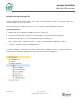
evc/epc Controller With SAE J1939 Interface Using the evc/epc with your PC Install the Graphical User Interface (GUI) on a host PC. Use the default file locations for easy future update. The user has the option to choose file location. Don’t run the GUI from a network as it needs access to certain files only in the Windows directories. System Requirements Windows XP, Vista or Windows7, 100MB or greater free disk space. Insert the CD and follow the instructions.
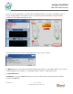
evc/epc Controller With SAE J1939 Interface The evc/epc can be powered by a +5V USB to allow configuration without connecting to a 12/24VDC system. A message “Supply Voltage is Low” appears on the screen. The user may communicate, change, and save settings to the unit without driving the coil(s). At start up the GUI searches the PC communication ports for the evc/epc controller. The MAC ID determines the module’s Command and Status PGN addresses on the SAE J1939 bus.
evc/epc Controller With SAE J1939 Interface evc/epc GUI Overview File All changes made through the GUI are temporary until saved permanently. Permanently save settings to unit: Save the settings to the unit’s EEPROM (permanent memory). Permanently save settings to unit & file (.dat): Permanently save the settings to the unit’s EEPROM and to a data file that may be uploaded into any evc/epc controllers later. Settings will be lost if not permanently saved before power cycle.
evc/epc Controller With SAE J1939 Interface Default Settings There are four default modes of operation. Other modes of operations can be created using data files. 1. 2. 3. 4. HP Limiting or Anti-Stall with Fixed Command HP Limiting or Anti-Stall with Variable Command Single Coil Pump or Valve Control Dual Coil Pump or Valve Control Environment The Environment Menu selects the terminology for various markets.
evc/epc Controller With SAE J1939 Interface Help Reconnect with controller: The GUI will reset communication with the module, and re-read and update all variables. Print Settings to text: Will print all settings to your PC default printer, or print to a text file, tab delimited. The text file may be viewed with Notepad, Word, or Excel. About Controller: Will display information about the evc/epc, the GUI revision, serial number, contact information etc.
evc/epc Controller With SAE J1939 Interface Each graph tracks two variables that are individually scaled. Select the variable from the Pull Down Menus. “Y” axis is automatically scaled to the respective minimum and maximum values. To customize the scaling, simply select a value on the graph and enter the desired value. Data Logging “Log Data” and save it in “.xls” format. The data file size is only limited by the PC hard-drive capacity.
evc/epc Controller With SAE J1939 Interface Example data files are saved to your PC during the installation. When loading factory default data files, select “Environment”, then select the desired default file. Default Data files will overwrite any settings in the unit. Adjust the Coil Settings first, then other settings as needed. In Agriculture or Automotive you will have Four files: 1. HP Limiting with Variable Command /Anti-stall with Variable Command.
evc/epc Controller With SAE J1939 Interface Dashboard PWM% A/B – displays the PWM duty cycle output for coil A and B. The PWM% B will be “Grayed Out” when Coil B is disabled. % Demand A/B – displays the percent of demand for the output with respect to the Maximum and Minimum Current settings. The % Demand B will be “Grayed Out” when Coil B is disabled. Coil Current A/B – displays the output current. The Coil B Current will be “Grayed Out” when Coil B is disabled.
evc/epc Controller With SAE J1939 Interface Output A or B Coil Settings Select Coil B Active for a Dual Coil Valve Control. Enter minimum, maximum current and dither frequency according to the valve specification. Enter UP or DOWN ramp times. “Change Settings” to apply the changes to the unit’s temporary memory. Once the system is running, fine tune these settings. Always Active (ON) – Output A is always active and cannot be set “OFF”. Coil B – active (ON/OFF) – Enables/Disables Output B.
evc/epc Controller With SAE J1939 Interface Coil A/B Min Current (0 to 2.5Amps) Determines the min current or duty cycle. Fine tune this value to balance machine safety and valve responsiveness. Typical values for this can be found in the manufacturer’s information. Coil A/B Max Current (0 to 3Amps) When Current Feedback is “ON”, it determines the max output current. Typical values can be found in the valve manufacturer’s information.
evc/epc Controller With SAE J1939 Interface Ramp Up (1 to 65,000 Mini Seconds) – Determines the time for Output A or B to ramp UP from minimum to maximum current. Ramp Down (1 to 65,000 Mini Seconds) – Determines the time for Output A or B to ramp Down from maximum to minimum current. Coil A&B PWM Hz (33 to 500Hz) – This is the PWM or Dither frequency according to the valve spec. (Sun cartridges are 140Hz).
evc/epc Controller With SAE J1939 Interface Manual Mode Caution All settings on this tab are temporary and will immediately affect the outputs. In manual mode all limits and controls are bypassed. The evc/epc goes back to normal operation when exiting the GUI in manual mode. Cycling power on the unit will reset the controller and remove manual override. “Manual Mode” provides a quick method of testing the outputs.
evc/epc Controller With SAE J1939 Interface Command & Error Settings Analog Input Active (On/Off) – Enables/Disables the command analog input. Analog Center Active (On/Off) When enabled, the “Pot Center Voltage” becomes the zero demand point. Coil A is driven from the center voltage to the max voltage and coil B is driven from the center voltage to the min voltage This setting is used in Dual Coil Valve Control only.
evc/epc Controller With SAE J1939 Interface Command Input Selection 0-5VDC 0-10VDC 4-20mA Inverted – reverses the response of the command input to output current. i.e., Minimum command input will give 100% output current and the Maximum command input gives 0% output current. For industrial applications that use ±5VDC or ±10VDC, please use a HCT Command Signal Conditioner with the evc/epc controller. CSC-0505 – accepts ±5VDC and converts to 0-5V. CSC-1005 – accepts ±10VDC and converts to 0-5V.
evc/epc Controller With SAE J1939 Interface Dead band The Dead band can only be used when the Analog Center Active is “ON”. Dead band is split one half above, one half below the center point. 0.2VDC means coil A output current starts at 2.6VDC, coil B output current starts at 2.4VDC. Pot Maximum It sets the max command input to have the maximum current. If the command input is > POT Maximum + the Command Margin, the evc/epc will declare an error and the outputs go to the default settings.
evc/epc Controller With SAE J1939 Interface Pulse/AIN 2 Settings Pulse Input Selections (Analog or Pulse) – Select analog to use this input as analog input 2 for dual valve control or select pulse to use this input as the pulse input for anti-stall function. 0-5V, 0-10V & ±1V (Enabled/OFF) – Select the voltage range that matches the analog input signal. The ±1V only applied to Pulse input. For anti-stall function, match the voltage range to the Pulse Pick UP.
evc/epc Controller With SAE J1939 Interface Global Settings Enable Auto-Reverse (On/Off) When in HP Management or Anti-Stall mode, if the measured RPM is ≤ RPM Stop or No Load RPM, coil A current ramps down to 0, and then coil B current ramps up to the Reverse Set- point. The module will try to restart normal operation after the reverse cycle completes. Reverse Time (0 to 65 Sec) – It sets the time that coil B will remain in reverse during an Auto-Reverse cycle.
evc/epc Controller With SAE J1939 Interface Factory Settings (Only available with the OEM password) Reset Unit It restores the controller to the last permanently saved configuration. Serial Number Specific for this unit, reference to the factory record. Start Date The date when the evc/epc is connected to the GUI for the first time. OEM Password When the GUI is purchased, the initial password is included. If lost, please contact HCT. Users may change the OEM password.
evc/epc Controller With SAE J1939 Interface SAE J1939 Set Point A or B % and Set Point RPM A SAE J1939 message can set the demand for coil A and B. Measured RPM The evc/epc controller can accept an SAE J1939 message containing the measured engine RPM on PGN: 0xF004 (61444) Source Address (SA): 0x00. Timeout The box is red when the SAE J1939 message has timed out indicating a bus, connection or data error.
evc/epc Controller With SAE J1939 Interface Operational Modes Single Coil Valve or Pump Control Only Coil A is used in this function. 0-5VDC gives coil A 0-100% current output. Coil A Current max min 0 min max Command Voltage 023-00354-Rev1.6 evc/epc User Manual Copyright © High Country Tek, Inc.
evc/epc Controller With SAE J1939 Interface Dual Coil Valve or Pump Control One Valve with coil A and B when Center Active is ON Coil B Current Center (2.5/5V) Coil B max Coil A Current Coil A max Coil B min Coil A min Analog Center Active (Enabled/OFF) – when enabled, 0-2.5VDC drives coil B, 2.5-5VDC drives coil A. POT Center Error Detection at Initial Turn On (Enabled/OFF) – when enabled, we have a neutral start position for machine safety. 5/10V 0 Min 023-00354-Rev1.
evc/epc Controller With SAE J1939 Interface One Valve with coil A and B when Coil Selection is ON Coil A Current Coil B Current max max min min 0 min max Command Voltage 0 min max Command Voltage Coil Selection Active (Enabled/OFF) – when enabled, Analog Center Active is automatically turned OFF. 0-5V gives both coils 0-100% PWM current output. But there is only one output at one time. When the digital input 2 is OFF, coil A is working. When the digital input 2 is ON, coil B is working.
evc/epc Controller With SAE J1939 Interface Two Valves, Coil A for Valve 1, Coil B for Valve 2 Coil A Current Coil B Current max max min min 0 min max Command Voltage 0 min max Analog Input 2 Voltage Coil A and B are independently controlled by 2 Potentiometers or Joysticks. Coil A follows the Command Volts. Coil B follows the Pulse Volts because the pulse input Pin is used as the Analog input 2. 0-5V gives both coils 0-100% PWM current output. But there are two outputs at the same time.
evc/epc Controller With SAE J1939 Interface Anti-Stall or Horsepower Management With Fixed Command The Anti-Stall function reduces the current to prevent the engine from stalling during a sudden external load increase. The fixed set-point determines the max forward speed of the work function. The reverse set-point determines the max reverse speed of the work function. At start-up the measured RPM must initially reach the “RPM Slow” set-point to allow the evc/epc to ramp up Coil A.
evc/epc Controller With SAE J1939 Interface When the measured RPM is above the “RPM Slow” (1900RPM), Coil A current is determined by the Fixed Setpoint. When the measured RPM starts to drop below the “RPM Slow”, Coil A current is reduced proportionally to the measured RPM. Coil A current becomes zero when the measured RPM reaches “RPM Stop” (1800RPM) or below.
evc/epc Controller With SAE J1939 Interface Anti-Stall or Horsepower Management With Variable Command This mode is similar to the “Anti-stall with Fixed Command” or “Horsepower Management with Fixed Command”. The only difference is that this function allows a variable command input to control the forward speed of the work function. The max reverse speed of the work function is set by the GUI. The input can be from an external POT, a joystick or a SAE J1939 message.
evc/epc Controller With SAE J1939 Interface Dual Output With Over Speed Protection It works with dual fixed displacement pumps and switches valves ON or OFF according to the measured RPM. The measured engine RPM can be from the alternator ‘R’ terminal, PPU, or SAE J1939. BOTH outputs are ON when below ‘A’ setting. When the measured RPM ≥ Set-point A RPM, coil A ramps down to minimum current.
evc/epc Controller With SAE J1939 Interface Constant Flow Mode Constant Flow Mode operates with a variable displacement pump. It reduces the output of coil A to reduce the pump displacement when the engine rpm increases, maintaining constant flow output of the pump. When the measured RPM is 1500rpm, output A provides max current. When the measured RPM is 1800rpm, output A provides 0 current. 023-00354-Rev1.6 evc/epc User Manual Copyright © High Country Tek, Inc.
evc/epc Controller With SAE J1939 Interface Closed Loop Speed Control The “evc Closed Loop” Graphical User Interface must be selected. Set the coil min, max current and the PWM frequency according to the valve specification. The reference and the feedback can be set by either of the command voltage, pulse voltage, pulse rpm, J1939, etc. In this example, the reference A is set by the command voltage. The feedback is set by the pulse rpm. The maximum displayed RPM is for the display only.
evc/epc Controller With SAE J1939 Interface When the measured rpm increases to above 1900rpm, the evc/epc will reduce the current to maintain 1900rpm until it reaches 0. The closed loop control is a dynamic process. The evc/epc constantly changes the current to maintain the reference rpm. If the overshoot of the speed is big, the changing rate of the current is fast. If the overshoot of the speed is small, the changing rate of the current is slow.
evc/epc Controller With SAE J1939 Interface SAE J1939 CAN Bus The evc/epc can be controlled by messages received over the SAE J1939 Bus. The EEC1 (PGN: 61444 SA: 0) engine RPM (SPN: 190) can be monitored for use in anti-stall and closed loop operations. The proprietary SAE J1939 Command Message (PGN: 65281 through 65407 SA: 34) can be monitored for Coil A, Coil B and RPM Set points for various operation modes. This address is adjusted based on the Module ID.
evc/epc Controller With SAE J1939 Interface Status Message Format Transmission Cycle Time Data Length Data Page PDU Format PDU Specific Priority Parameter Group Number 100mS 8 0 255 Module ID + 128 3 65409 Through 65535 (FF81 Through FFFF) Status Message Start Position 1 2.1 2.2 2.3 2.4 2.5 2.6 2.7 2.8 3.1 3.2 3.3 3.4 3.5 3.6 3.7 3.8 4.1 4.2 4.3 4.4 4.5 4.6 4.7 4.8 5-6 7-8 023-00354-Rev1.
evc/epc Controller With SAE J1939 Interface Analog Values Message Start Position 1 2-3 4 5-6 7 8 Length 1 Byte 2 Bytes 1 Byte 2 Bytes 1 Byte 1 Byte Parameter Name Always = 2 (Analog Value) Command Input Value (volts x100 or mA x100) 0 = Command Volts, 1 = Command mA Pulse Input volts x100 Always = 0 Always = 0 Parameter Values Coil n Set point Data Length Resolution Data Range Operational Range 2 Bytes 0.
evc/epc Controller With SAE J1939 Interface Module Id Command PGN 1 2 3 4 5 6 7 8 9 10 11 12 13 14 15 16 17 18 19 20 21 22 23 24 25 26 27 28 29 30 31 32 33 34 35 36 37 38 39 40 41 42 43 FF01 FF02 FF03 FF04 FF05 FF06 FF07 FF08 FF09 FF0A FF0B FF0C FF0D FF0E FF0F FF10 FF11 FF12 FF13 FF14 FF15 FF16 FF17 FF18 FF19 FF1A FF1B FF1C FF1D FF1E FF1F FF20 FF21 FF22 FF23 FF24 FF25 FF26 FF27 FF28 FF29 FF2A FF2B 023-00354-Rev1.
evc/epc Controller With SAE J1939 Interface Problems installing the Communication Port Adapters Windows does not like Com ports with the same name, and some devices might hang onto a com port when not in use. Here is how to clean and remove problem ports. Option 1 Devices that have been installed but are not currently available are "phantom devices". These devices are not usually displayed in the device manager, but can be made to be displayed.
evc/epc Controller With SAE J1939 Interface "DevMgr_Show_NonPresent_Devices" and set the value to 1, then click OK. Close the System Properties panel. Open the Device Manager "View” Show Hidden Devices". Device Manager will show all hidden and phantom devices. Uninstall the phantom devices by right clicking on them, and 'delete'. Reboot the PC. When you connect PC to the unit, give the computer time to find and install the driver.
evc/epc Controller With SAE J1939 Interface Minin icul u e lo a ion ane li eu e on e-c clin uc ion - oad e icle Fo e ood ul ecla a ion il Field al a e and De oli ion oolin aau ecial e e oe o e i In e al e en olu ion Mili a ui on ol ene a ion ion on ol For a full list of authorized distributors worldwide, please visit a ed D i e u on ol c con ol co di i uo inde For customer service, pricing, order placement and application support, cont