MVP-F Closed-loop Controller MVP-F Closed-loop Proportional Valve Controller High Country Tek, Inc. reserves the right to improve this product at any time and without notice. This manual may contain mistakes and printing errors. The content is regularly checked and updated. Please check our website or contact our customer support for latest version. HCT accepts NO liability for technical mistakes or printing errors or their consequence.
MVP-F Closed-loop Controller Content Welcome .................................................................................................................................................................... 3 Product Application Guidelines .................................................................................................................................. 4 MVP-F Controller ......................................................................................................................
MVP-F Closed-loop Controller Welcome Welcome to High Country Tek Inc. HCT is North America’s foremost independent designer and producer of modular, ruggedized digital and analog electronic controllers for the fluid power industry. From our factory in California, we manufacture ‘specialty’ controllers for specific functions and the user programmable ‘DVC family’ to enable large area networked system solutions. The modules are used in mobile, industrial and marine applications.
MVP-F Closed-loop Controller Product Application Guidelines ALWAYS do the following FULLY read this manual and accompanying data sheets BEFORE starting. Isolate this unit from all other equipment BEFORE any form of welding. Isolate the controller from ANY form of battery charging or battery boosting. Be aware of the electrical & mechanical connections, and the expected reactions of the equipment. Operate the units within the temperature range. Use the correct tools to do the job (i.
MVP-F Closed-loop Controller MVP-F Controller The MVP-F controller drives proportional solenoid valves in a closed loop system to follow a command signal. When the feedback is greater than the command input, the coil receives full current; when the feedback is less than the command input, the coil receives no current. Once configured, the settings are permanently stored in the controller memory.
MVP-F Closed-loop Controller Physical Description There are two indicator LEDs: STATUS and OUTPUT. The STATUS LED is green when the applied voltage is within the operating range. The OUTPUT LED is yellow and the brightness will vary with the output current. In the case of a fault the STATUS LED will flash red with a flash code. See Fault Status for details. The MVP communicates with the Graphical User Interface through an infrared interface port to RS232.
MVP-F Closed-loop Controller Configuration The GUI has 4 buttons (ran from a PC): Lock, Unlock, Up, and Down. There are short-cut keys: ‘/’(lock), ‘*’(unlock), ‘+’(up), and ‘-‘(down). The HCT hand held interface has the same 4 buttons and a liquid crystal display. Use the up and down arrows to navigate through the parameter list. The display will show the next parameter in the list when pressed. The parameter name is on the first line and the value is on the second line.
MVP-F Closed-loop Controller “Read settings from controller” displays a static table of values from non-volatile memory. The changes made to the settings by selecting “lock” are not updated in the table unless “read settings from controller” is selected again. To save the settings into a file for future use, click “read settings from controller” before clicking “save settings to file”. 021-MVP-F Rev A MVP-F User Manual Copyright © High Country Tek, Inc.
MVP-F Closed-loop Controller When uploading settings from a data file, the static table shows the settings from the data file, but they are not in the controller yet. Click “write settings to controller” before clicking “read settings from controller”. After this step, the static table displays the MVP settings from the data file. 021-MVP-F Rev A MVP-F User Manual Copyright © High Country Tek, Inc.
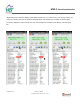
MVP-F Closed-loop Controller Parameter List The following table outlines the MVP-F parameters as well as the limits and units of measure for each parameter. Parameter Limits Units MVP-Fxx-xxx Version # Mode See Mode Description Mode # Proportional gain 0 to 100 % Integral gain 0 to 100 % Derivative gain 0 to 100 % PID loop time 1 to 30 # cycles Dither frequency 50, 75, 100, 125, 150, 175, 200, 225, 250, 275, 300, 350, 400, 500, 1000 Hz Minimum command 0 to 10.0 (0 to 20.
MVP-F Closed-loop Controller MVP-Fxx - The title parameter is fixed. It displays the model number and the firmware version. MODE - Three modes of operation. 1. Normal – standard operating mode where increasing output results in increasing feedback. 2. Inverse – the inverted mode where increasing output results in decreasing feedback. 3. Open loop – the feedback is not used and the output current is proportional to the command. PROPORTIONAL GAIN – Sets the P term in a PID control loop.
MVP-F Closed-loop Controller CMD BELOW MIN CMD ABOVE MAX FDBK BELOW MIN FDBK ABOVE MAX 1. Off – will place the output in the OFF state. 2. Limit – will hold the command to the respective settings. 3. Fault – will trigger the corresponding fault causing the controller to shut down. 1. Off – will place the output in the OFF state. 2. Normal – will use the normal feedback signal 3. Fault – will trigger the corresponding fault causing the controller to shut down.
MVP-F Closed-loop Controller PID Algorithm The PID algorithm is a digital, velocity style PID as shown: O(t) = O(t-1) + P*(e(t)-e(t-1)) + I*T*e(t) + D/T*(e(t) + e(t-2) – 2*e(t-1)) Where: O = output P = proportional gain term I = integral gain term D = derivative gain term e = error at time t T = PID loop time. Setup Procedure The following steps are recommended when commissioning an MVP-F controller: 1. Set the min, max outputs and dither frequency according to the valve specification.
MVP-F Closed-loop Controller MVP-F closed-loop control: Place the controller in Mode 3 – Open loop to fine tune the min and max feedback range. 021-MVP-F Rev A Place the controller in Mode 1 – Normal When command (4.84V) is greater than the feedback (1.28V), the MVP-F will output max current (600mA). MVP-F User Manual Copyright © High Country Tek, Inc. – 2013 When command (1.04V) is less than the feedback (1.32V), the MVP-F will output 0 current.
MVP-F Closed-loop Controller Wiring Order Information The following is a break-down of the MVP part numbering system: MVP-F1V-06A-10F 10F = 10ft cable 20F & 30F standards 06A = 600mA output 12A = 1200mA output 25A = 2500mA output F1V = 0-10V input F2A = 4-20mA Required Communication Cables: For the Hand Held Interface Device: P/N: CBL-IRA For the PC software SAM: PN: CBL-IRMU P/N: CBL-IRA 021-MVP-F Rev A P/N: CBL-IRMU MVP-F User Manual Copyright © High Country Tek, Inc.
MVP-F Closed-loop Controller Application Examples Single Solenoid Control The MVP can drive a single solenoid with a signal of 0-5VDC, or 0-10VDC, or 4-20mA. Use Mode 3 “open loop” to determine the max feedback range. Use Mode 1 “Normal” for closed-loop application. Set the dither and output settings according to the valve specifications. +V Power Input 9 - 28VDC FUSE Brown PWR + Feedback White Enable +5VDC @ 2mA Red Ref.
MVP-F Closed-loop Controller Plug - - For a full list of authori ed distributors worldwide, please visit For customer service, pricing, order placement and application support, contact us through E-mail at A UN Hydraulics C ompany 2 old Flat Court Nevada City, CA, 5 5 Tel ( ) 53 2 5 323 Fax ( ) 53 2 5 3275