PV200 Closed Loop Proportional Valve Controller PV200 Closed-loop Proportional Valve Controller High Country Tek, Inc. reserves the right to improve this product at any time and without notice. This manual may contain mistakes and printing errors. The content is regularly checked and updated. Please check our website or contact our customer support for latest version. HCT accepts NO liability for technical mistakes or printing errors or their consequence.
PV200 Closed Loop Proportional Valve Controller Contents Welcome .................................................................................................................................................................... 3 Product Application Guidelines .................................................................................................................................. 4 PV200 Controller ..................................................................................................
PV200 Closed Loop Proportional Valve Controller Welcome Welcome to High Country Tek Inc. HCT is North America’s foremost independent designer and producer of modular, ruggedized digital and analog electronic controllers for the fluid power industry. From our factory in California, we manufacture ‘specialty’ controllers for specific functions and the user programmable ‘DVC family’ to enable large area networked system solutions. The modules are used in mobile, industrial and marine applications.
PV200 Closed Loop Proportional Valve Controller Product Application Guidelines ALWAYS do the following FULLY read this manual and accompanying data sheets BEFORE starting. Isolate this unit from all other equipment BEFORE any form of welding. Isolate the controller from ANY form of battery charging or battery boosting. Be aware of the electrical & mechanical connections, and the expected reactions of the equipment. Operate the units within the temperature range.
PV200 Closed Loop Proportional Valve Controller PV200 Controller The ProValve200 controller drives proportional solenoid valves in a closed loop system. When the feedback is greater than the command, coil A receives current; when the feedback is less than the command, coil B receives current. The current is proportional to the difference between the command input and the feedback. Once configured, the settings are permanently stored in the controller memory.
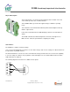
PV200 Closed Loop Proportional Valve Controller Physical Description The boxed numbers 1 to 16 represent the terminal positions. A label on the side of the module provides a list of terminal functions. The “POWER” LED is green when the applied voltage is within the operating range. The “OUTPUT A” and “OUTPUT B” LEDs are yellow and the brightness will vary with the output current. In the case of a fault the “FAULT” LED will display solid red. See Fault Status for details.
PV200 Closed Loop Proportional Valve Controller Configuration The GUI has 4 buttons (ran from a PC): Lock, Unlock, Up, and Down. There are short-cut keys: ‘/’(lock), ‘*’(unlock), ‘+’(up), and ‘-‘(down). The HCT Hand Held Interface has the same 4 buttons and 2-line LCD. Use the up and down arrows to navigate through the parameter list. The display will show the next parameter in the list when pressed. The parameter name is on the first line and the value is on the second line.
PV200 Closed Loop Proportional Valve Controller “Read settings from controller” displays a static table of values from non-volatile memory. The changes made to the settings by selecting “lock” are not updated in the table unless “read settings from controller” is selected again. To save the settings into a file for future use, click “read settings from controller” before clicking “save settings to file”. 021-PV200 Rev A PV200 Uses Manual Copyright © High Country Tek, Inc.
PV200 Closed Loop Proportional Valve Controller When uploading settings from a data file, the static table shows the settings from the data file, but they are not in the controller yet. Click “write settings to controller” before clicking “read settings from controller”. After this step, the static table will display the PV200 settings from the data file. 021-PV200 Rev A PV200 Uses Manual Copyright © High Country Tek, Inc.
PV200 Closed Loop Proportional Valve Controller Parameter List This table outlines PV200 parameters, the limits and units for each parameter. Parameter Limits Units PV200 Version # Proportional gain 0.0 to 100.0 % Integral time 0.0 to 2.5 Sec Derivative gain 0.0 to 100.0 % Target deadband 0.0 to 25.0 % Invert target Yes/No NA Target minimum 0.0 to 100.0 % Target maximum 0.0 to 100.0 % Position minimum 0.0 to 100.0 % Position maximum 0.0 to 100.0 % A Minimum output 0.0 to 2.
PV200 Closed Loop Proportional Valve Controller PV200 - The title parameter is fixed. It displays the model number and the firmware version. PROPORTIONAL GAIN – Sets the P term in a PID control loop. It is a multiplication of the error added to the output. The higher the setting, the faster the response will be. Also, higher settings result in shorter ramp time, but it can cause oscillation. It is variable type. INTEGRAL TIME – Sets the I term in a PID control loop. It is the sum of the error over time.
PV200 Closed Loop Proportional Valve Controller B MAXIMUM OUTPUT - Sets the maximum output current for coil B (Amps). The value in the brackets is the present output current. B OVERRIDE - Sets the output current for a digital reverse override command. No ramping takes place during override operations. The value in the brackets is the present output current. DITHER FREQ. - Set the PWM or dither frequency according to the valve specifications. This parameter is variable.
PV200 Closed Loop Proportional Valve Controller PID Control The PV200 utilizes a PID control loop algorithm. PID control uses process feedback to correct for error. The error correction factors are proportional, integral, and derivative. In the PV200, the error is the difference between the target and actual position inputs. This error is fed into the PID loop which results in a signal to drive one of the two solenoid outputs. The output causes a change in position and therefore reduces the error.
PV200 Closed Loop Proportional Valve Controller PV200 closed-loop control: When the actual position (65%) is greater than the target position (56%), coil A receives 0.22A current. When the actual position 24%, is less than the target position 56%, coil B receives 0.45A current. Notice that the current is proportional to the difference between the actual position an the target position. 021-PV200 Rev A PV200 Uses Manual Copyright © High Country Tek, Inc.
PV200 Closed Loop Proportional Valve Controller Before switching the “reverse override” ON, coil B current is 0.68A because the actual position is 0%, less than the target position 56%. 021-PV200 Rev A After switching the “reverse override” ON, the PV200 becomes an open loop controller, coil B current is set to the override current setting of 0.5A. PV200 Uses Manual Copyright © High Country Tek, Inc.
PV200 Closed Loop Proportional Valve Controller Switch the “reverse override” OFF and switch the “forward override” ON. The PV200 becomes an open loop controller. Coil A current is set to the override current setting of 0.5A. By switching OFF both override inputs, the PV200 resumes normal closed-loop operation and coil B current is 0.68A because the actual position 0% is less than the target position 56%. The Reverse override has a higher priority than the forward override.
PV200 Closed Loop Proportional Valve Controller Wiring Terminal connections are listed in the table below.
PV200 Closed Loop Proportional Valve Controller Order Information The following is a break-down of the PV200 part numbering system: PV200-XX-X Blank = 2.5A max output -L = 500mA max output 24 = 24VDC digital inputs 115 = 115VAC digital inputs 230 = 230VAC digital inputs Required Communication Cables: For the Hand Held Interface Device: P/N: PCA-1 For the PC software SAM: PN: PCA-1 and P/N: 108-00119 P/N: PCA-1 021-PV200 Rev A P/N: 108-001119 PV200 Uses Manual Copyright © High Country Tek, Inc.
PV200 Closed Loop Proportional Valve Controller Application Examples Dual Solenoid Control The PV200 can drive two solenoids for closed-loop position control. Set the dither and output settings according to the valve specifications.
PV200 Closed Loop Proportional Valve Controller - - For a full list of authori ed distributors worldwide, please visit: For customer service, pricing, order placement and application support, contact us through E-mail at: A SUN Hydraulics C ompany 20 old Flat Court Nevada City, CA, Tel: (1) 0 2 2 Fa :(1) 0 2 2