Mini Controller for the Xenon Strobe Fixture User’s Manual ® TM S Y S T E M S . High End Systems Inc. 2217 West Braker Lane Austin, Texas U.S.A.
© High End Systems, Inc. 1995, All Rights Reserved Information and Specifications in this document are subject to change without notice. High End Systems, Inc. assumes no responsibility or liability for any errors or inaccuracies that may appear in this manual. Unlawful reproduction or distribution in any manner without the written permission of High End Systems is strictly forbidden. .
Table of Contents Introduction....................................................................................Intro-1 About This Manual ....................................................................................... Intro-1 Text Style ...................................................................................................... Intro-1 Caution and Warning Symbols ................................................................ Intro-1 Safety Instructions .................................
Audio Mode ........................................................................................................ 2-7 Audio Parameters........................................................................................... 2-7 Audio Rate or Intensity Manipulation ........................................................... 2-8 Appendix A Troubleshooting and Maintenance.................................................... A-1 Support Checklist..............................................................
Table ADM.4 Available Programs for Four Fixtures ...................................ADM-4 Table ADM.5 Available Programs for Five Fixtures....................................ADM-5 Table ADM.6 Available Programs for Six Fixtures .....................................ADM-6 Table ADM.7 Available Programs for Seven Fixtures .................................ADM-7 Table ADM.8 Available Programs for Eight Fixtures ..................................ADM-8 Table ADM.9 Available Programs for Nine Fixtures .............
TOC-4 Mini Controller User’s Manual
Introduction Congratulations and thanks for selecting the Mini Controller for the DATAFLASH® AF1000 Xenon Strobe Fixture from Lightwave Research®. About This Manual This manual provides the means to setup and operate Mini Controller. This manual is organized in the following sections: Introduction—introduces you to this manual, the Mini Controller, provides hardware specifications, and technical support information. Chapter 1 Installation and Setup—explains how to install the Mini Controller.
Safety Instructions • • Heed all caution and warning messages throughout this manual and the documentation that accompanies your AF1000 strobes. Servicing must be conducted by the manufacturer or other qualified service personnel. There are no user serviceable parts inside. Overview The Mini Controller for the DATAFLASH AF1000 strobes is a powerful compact device that can control up to 12 channels of AF1000 strobes through 24 channels of USITT DMX-512 protocol.
Getting Help High End Systems Service provides a help line should you encounter any problems during your installation or initial operation. Currently, service hours are 9 a.m. to 6 p.m. (Central), Monday through Friday.
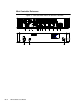
Mini Controller Reference Figure 1.
1. disables controller output of programs 2. when held down, causes all connected strobes to flash at full intensity for .15 seconds at 50 Hz. and .125 seconds at 60 Hz. 3. Up/down arrow keys increments values up/down 4. provides access to current program, Program Advance Mode, and Program Hold Mode 5. provides access to the Rate parameters 6. provides access to the Intensity parameters 7.
Intro-6 Mini Controller User’s Manual
Chapter 1 Installation and Setup 1 In this chapter you will: ❑ unpack the Mini Controller ❑ configure AF1000 strobes ❑ configure Mini Controller ❑ install the controller’s cables Unpacking In this section you unpack your Mini Controller and verify that it arrived complete and without any damage. Save the Shipping Materials Do not discard the shipping cartons and packing materials. These cartons and packing materials are specifically designed to protect the controller during transport.
Before You Begin Caution: Before you begin the installation read the following safety precautions. 1. Read all warnings, precautions, and safety instructions listed in AF1000 User Manual. 2. Check the label on the back of the controller to ensure that the voltage is correct for your location. 3. Do not place the Mini Controller on the same circuit with the AF1000 strobes, as doing so may result in erratic actions by the controller. 4. Do not use DATAFLASH strobes with this controller.
Next, each strobe must be set for two channel DMX mode. This is accomplished by setting Personality switches <3> and <4> to the On position (switch <5> must be in the off position). 1 Finally, set the fixture address switches to 1–23 (depending upon how many fixtures you have). Refer to Table 1.2 for the appropriate settings. Table 1.
Mini Controller Switch Settings The DIP switches on the Mini Controller must be properly set so the controller can send the correct data packets to the number of available fixtures. If power has already been applied to the controller, the seven-segment LEDs will blink C F (configure) until a DIP switch is set. The DIP switches are located on the front panel of the Mini Controller in the lower right-hand corner. Refer to Figure 1.1. Figure 1.1.
Connect an XLR cable to the rear of the Mini Controller and run it to the first AF1000. Daisy chain the desired number of fixtures together. Refer to Figure 1.3. Note: fixture termination is not required. 1 Figure 1.3.
Connect the other end of the cable to an unused audio mixer output. Refer to Figure 1.5. Figure 1.5. Connecting the Audio Cable Caution: Never connect a speaker level signal (cable from an amplifier output) to the Audio input on the Mini Controller. Component damage will occur and this action will void your Warranty! The line level should be from 100 mV to a maximum of 1 V peak to peak. Note: a built in summing circuit combines the left and right signals together.
Chapter 2 Mini Controller Operation In this chapter you will: ❑ learn to operate the Mini Controller ❑ learn how to select the desired program ❑ learn about the Mini Controller’s special features ❑ learn how to change the Rate, Intensity, and Audio programs to cater to your needs 2 Overview This Chapter covers the operation of the Mini Controller and the functions of the keys.
Figure 2.1. Mini Controller Operation Process When a Program is run, it is run from the first step to the last step. Then the Program will loop back to the first step and begin this process again. Standby Mode When power is first applied to the unit or when the unit is reset, Standby Mode is automatically engaged. The Mini Controller is in Standby Mode when the LED above the < STANDBY> key is illuminated. Standby mode is used to allow the desired program to be located without starting any other program.
Program Hold Program Hold allows another program to be selected without affecting the current program being run. Program Hold is initiated by holding down the < program> key and using the arrow keys to pre-select another program. The Program Hold Indicator (LED between the 7-segment LEDs in the value display) will illuminate to confirm this mode is active. The next program will not begin until the < program> key is released.
Random Function Programs Immediately following the Standard Programs are three Random Function Programs. This set of programs is not dependant upon the number of assigned channels. Random Function Programs are annotated by F 1 , F 2 , and F 3 on the value display. This set of programs perform the following actions: • • • –multiple fixtures will flash in a random pattern, but only one fixture will flash at maximum Intensity at a time.
Intensity The < intensity> key changes the brightness of the AF1000 strobes. There are three sets of Intensity parameters: Incremental, Program Functions, and Function Advance. 2 Incremental There are 64 Incremental Intensity parameters. These parameters are annotated on the display by 1 through 6 4 , with 1 being the dimmest and 6 4 being the brightest. Program Function Following the Incremental parameters, there are seven Program Function parameters. Refer to Table 2.
Rate The < rate> key allows access to the Rate at which the controller advances steps within every program. There are three sets of Rate parameters: Incremental, Program Functions, Function Advance. Incremental There are 99 Incremental parameters for Rate. These parameters are annotated on the display by 1 through 9 9 , with 1 being the slowest Rate and 9 9 being the fastest Rate. Program Function Following the Incremental parameters, there are seven Program Function parameters. Refer to Table 1.
Audio Mode The Audio feature allows audio triggering and synchronization control of the AF1000 strobes. Press the < audio> key and use the arrow keys to maneuver through the audio parameters. Note: if any of the following parameters are selected, Audio Mode will disable itself (- - ) so it will not to conflict with any actions of these parameters: • • • 2 Advance Programs (A 1 through A 8 ) in Program Mode. Program Function in Rate Mode and Intensity Mode. Function Advance in Rate or Intensity Mode.
Audio Rate or Intensity Manipulation Within each audio parameter, there are nine functions for Program, Rate and Intensity manipulation. These functions are annotated as 0 through 9 on the display. Refer to Table 2.3 and the Addendum for the purpose of these functions. Table 2.
Appendix A Troubleshooting and Maintenance This Appendix provides directions for troubleshooting problems that may have occurred from improper setup or configuration of the Mini Controller and the AF1000 strobes. Before calling for technical assistance, follow the recommended procedures in this Appendix to solve many of the common possible problems.
Possible Problems and Solutions Use the following Table to solve most problems. Table A.
Table A.
A-4 Mini Controller User’s Manual
Appendix B Warranty Information Limited Warranty Unless otherwise stated, your product is covered by a one year parts and labor limited warranty. If the warranty registration form provided with this equipment is filled out and faxed or mailed to High End Systems, Inc., and received within 60 days of invoice date, the one year parts and labor limited warranty will be extended one additional year, for a total of two years.
CONNECTION WITH ANY PRODUCT OR CAUSED BY PRODUCT DEFECTS OR THE PARTIAL OR TOTAL FAILURE OF ANY PRODUCT REGARDLESS OF THE FORM OF ACTION, WHETHER IN CONTRACT, TORT, (INCLUDING NEGLIGENCE), STRICT LIABILITY, OR OTHERWISE, AND WHETHER OR NOT SUCH DAMAGE WAS FORESEEN OR UNFORESEEN. Warranty is void if the product is misused, damaged, modified in any way, or for unauthorized repairs or parts. This warranty gives you specific legal rights, and you may also have other rights which vary from state to state.
Addendum This Addendum provides you with a listing of the current programs that are preinstalled on your Mini Controller. This Addendum will take precedence over any program information provided in the User’s Manual. Use the tables in the following sections for the description, location of available programs, and parameters of the Mini Controller.
Table ADM.
Table ADM.
Table ADM.
Table ADM.
Table ADM.
Table ADM.
Table ADM.
Table ADM.
Table ADM.
Table ADM.
Table ADM.
Random Function Programs Table ADM.13: Random Functions Display Description F1 multiple fixtures will flash in a random pattern, but only one fixture will flash at maximum Intensity at a time F2 single fixtures will flash in a random pattern and randomly go to full Intensity F3 all fixtures will flash in a random pattern, one fixture at a time (sequentially) at random intensities Advance Programs Table ADM.14: Advance Programs Display Description A1-A8 Standard Programs are randomly selected.
Intensity Parameters Use the following table for the descriptions of the parameters available through the < intensity> key. Table ADM.16: Intensity Parameters Display 1–64 Description 1 is the dimmest intensity and 6 4 is the brightest .
Audio Parameters Use the following table for the description of the parameters available through the < audio> key. Table ADM.
Display Description =9 program advancement every four beats, beat causes program to reset to the first step ≡0 program advancement every beat ≡1 program advancement every beat, step advancing on beat ≡2 ≡3 ≡4 ≡5 ≡6 ≡7 ≡8 ≡9 AA ADM-16 Mini Controller User’s Manual program advancement every beat, four steps advanced per beat program advancement every beat, beat causes maximum Rate, otherwise Rate is medium program advancement every beat, no program advancement, beat causes maximum Rate, tapers down