
DL.2 Digital Light User Manual


CHAPTER 17
Maintenance and Troubleshooting
218 DL.2 Digital Light User Manual
Fixture Head Driver Board
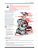
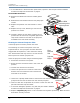
To replace the fixture head driver board:
1. Disconnect power to the fixture and allow it to cool.
2. Unlatch the two rear latches and remove the rear bezel.
3. Use a 3 mm allen wrench to remove the addressing screws and star washers.
4. Position new board against module aligning the center top standoff. Place contact screw(s)
in the appropriate position.
Note: When installing a replacement driver board on a module,
always
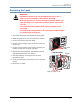
Gasket
place a star washer between an address screw
and the pad on the logic board to ensure good electrical
contact.
5. Carefully replace the rear bezel, making sure to place (but do
not force) the gasket over the lamp cover located on the back of
the projector.
6. Ensure that the fixture is on a solid surface. Select Calibrate
Motors through the Test_Home menu screen and leave the fixture undisturbed for 10
minutes while calibration occurs.
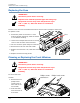
Replacing Fixture Base Driver Board
To replace motor driver board located in the fixture base housing:
1. Disconnect power to the fixture. If the fixture has been operating, allow the fixture to cool
before handling.
2. Loosen the two phillips head screws on menu display panel side of the Box cover
3. Loosen screws on menu display panel and gently open away from the fixture leaving the
harness cabling attached.
4. The driver board for pan functions and fans is located directly behind the display.
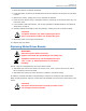
CAUTION!
The fixture will not function correctly if contact screws
are missing from driver boards.
5. After detaching all cabling, pull board out and replace.
6. Reattach cables.
7. Replace the side panel and top cover. Make sure you align the assembly properly when
inserting; damage to the fixture can result from improper alignment.
8. Ensure that the fixture is on a solid surface. Select Calibrate Motors through the
Test_Home menu screen and leave the fixture undisturbed for 10 minutes while calibration
occurs.