User Manual © High End Systems, Inc. 2004, All Rights Reserved Information and specifications in this document are subject to change without notice. High End Systems, Inc. assumes no responsibility or liability for any errors or inaccuracies that may appear in this manual.
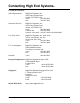
Contacting High End Systems® US and the Americas Sales Department: High End Systems, Inc. 2105 Gracy Farms Lane Austin, TX 78758 USA voice: 512.836.2242 fax: 512.837.5290 Customer Service: High End Systems, Inc. 2105 Gracy Farms Lane Austin, TX 78758 USA voice: 800.890.8989 24-hour fax: 512.834.9195 24-hour voice mail: 512.837.3063 or 800.890.8989 U.S. New York High End Systems, Inc. New York 311 W. 43rd Street, Ste 400 New York, NY 10036 voice: 210.957.6840 fax: 212.957.4466 U.S.
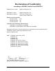
Declaration of Conformity according to ISO/IEC Guide 22 and EN45104 Manufacturer’s name: High End Systems, Inc. Distributor’s name: Distributor’s address: High End Systems, Inc. 2105 Gracy Farms Lane Austin, Texas 78758 USA Declares that the product Product Name: DL.
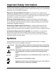
Product Modification Warning High End Systems products are designed and manufactured to meet the requirements of United States and International safety regulations. Modifications to the product could affect safety and render the product non-compliant to relevant safety standards. Mise En Garde Contre La Modification Du Produit. Les produits High End Systems sont conçus et fabriqués conformément aux exigences des règlements internationaux de sécurité.
Important Safety Information Instructions pertaining to continued protection against fire, electric shock, and injury to persons are found in Appendix A. Please read all instructions prior to assembling, mounting, and operating this equipment. Important: Informations De Sécurité. Les instructions se rapportant à la protection permanente contre les incendies, l’électrocution, excessif et aux blessures corporelles se trouvent dans l’Annexe A.
Patents This product may use one or more of the following patents: US 4,392,187; US 4,602,321; US 4,688,161; US 4,701,833; US 4,709,311; US 4,779,176; US 4,800,474; US 4,962,687; US 4,972,306;US 4,980,806; US 5,010,459; US 5,031,078; US 5,073,847; US 5,078,039; US 5,186,536; US 5,209,560; US 5,278,742; US 5,282,121; US5,307,295; US 5,329,431; US 5,331,822; US 5,367,444; US 5,402,326;US 5,430,629; US 5,432,691; US 5,454,477; US 5,455,748; US 5,506,762; US 5,515,254; US 5,537,303; US5,545,951; US 5,580,164; U
DL-1 is a highly complex and sensitive electro-optical device and care and thought in how it is used, rigged, and positioned will maximize the product’s life and your investment. Failure to follow these guidelines and carry out regular maintenance will void the warranty. Returning an Item Under Warranty for Repair. It is necessary to obtain a Return Material Authorization (RMA) number from your dealer or point of purchase BEFORE any units are returned for repair.
What You Should Know About Copyright Written By Suzy Vaughan Associates for High End Systems I want to use a film clip from "When Harry Met Sally" in a promotional piece advertising my services. What do I have to do to be able to do that? First of all, you need to obtain permission to use the clip from its owners. The clip is considered intellectual property, just as though it were your car or some software code developed by and belonging to Microsoft. This is because the U.S.
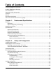
Table of Contents Contacting High End Systems® .................................................................................................... ii Product Modification Warning ......................................................................................................iv FCC Information .............................................................................................................................iv Important Safety Information ......................................................
Setting up the Link ............................................................................................................... 2-8 Installing a Terminator ......................................................................................................... 2-9 Powering On the Fixture ............................................................................................................. 2-9 Homing the Fixture......................................................................................
New Air Filter............................................................................................................... 3-13 Fixture Mode Menu ........................................................................................................... 3-14 Crossloading Fixture Software ................................................................................... 3-14 Test Options Menu..............................................................................................................
Effects ............................................................................................................................. 4-6 DL.1 Protocol Tables ................................................................................................................... 4-7 Standard DL.1 Protocol ........................................................................................................ 4-7 Enhanced DL.1 Protocol...............................................................................
List of Figures Figure 1-1: DL.1 Fixture Dimensions ................................................................................ 1-3 Figure 2-1: Figure 2-2: Figure 2-3: Figure 2-4: Figure 2-5: Figure 2-6: Figure 2-7: Figure 2-8: Figure 2-9: Video Connectors ............................................................................................. 2-2 RGBHV Connectors ......................................................................................... 2-3 Attaching the Mounting brackets ........
xiv DL.
Chapter 1: 1 Features and Specifications The DL.1 (Digital Light 1) fixture merges video projection and automated lighting technologies with a DMX controllable video light engine housed in a moving yoke fixture. DL.1 itself doesn't generate images; it is a mechanical means of displaying video images onto a stage with automated control of zoom, focus, and other videorelated parameters. DL.1 fixtures can be used in conjunction with the Catalyst Media Server and Catalyst Version 3.
Optional Digital Eye Technology • Captures digital video in light or dark settings and inputs directly into the graphic engine.
Specifications 1 Physical Specifications Figure 1-1 shows the DL.1 fixture as shipped: 343mm 512mm 305mm 595mm 176mm 538mm 861mm 445mm Figure 1-1 DL.1 Fixture Dimensions Dimensions: 861mm × 595mm × 343mm 33.9in. × 23.4in. × 13.5 in. Weight: 39 kg (85 lb) DL.
Electrical Specifications Warning: Class I equipment – This equipment must be earthed Input ratings: 100—120V 6.8A 50/60Hz, 200—240V 3.4A 50/60Hz Power factor: 0.94 Fuse: Power supply output fuse: 5A, 250V slow blow only.
Cable and Connector Specifications 1 Video Connectors: • RGBHV—BNC x 5 • VGA—DB15 • S-Video—mini-DIN DMX and RS-485 Projector Link Cables: Belden 9841 or equivalent (meets specifications for EIA RS-485 applications) with the following characteristics: • Two 4-conductor twisted pairs plus a shield • Maximum capacitance between conductors: 30 pF/ft • Maximum capacitance between conductor and shield: 55 pF/ft • Maximum resistance: 20 Ohm/100 ft • Nominal impedance: 100–140 Ohm Connectors: Two
1-6 Features and Specifications DL.
Chapter 2: Setup and Configuration 2 Unpacking the Fixture Your DL.1 fixture ships in a road case that is specifically designed to protect the product during transport. Unpack the DL.1 fixture and verify that it is undamaged. Inspect both the outside of the fixture and the projector for physical damage to components. Your DL.1 fixture ships with the following: • One road case • One DL.
Warning: Class 1 equipment - This equipment must be earthed. Installing a Line Cord Cap - U.K. Only In the United Kingdom, the colours of the cores in the mains lead of this equipment may not correspond with the colored markings identifying the terminals in the fixture’s plug.
Only one set of connectors at a time is active. You can set the active connectors using either the DL.1 menu system or the DMX protocol. To select an input, see “Menu Map” on page 3-4 first. Caution: Do not physically connect both the RGBHV and VGA connectors. Doing so can cause damage to the fixture and void the warranty. Figure 2-2 shows the RGBHV connectors in more detail: Vertical sync Horizontal sync Blue Green Red Figure 2-2 RGBHV Connectors The projector provided with the DL.
Mounting the Fixture Recommended Mounting Orientation High End Systems recommends mounting the DL.1 perpendicular to the floor, suspended vertically from a support system (such as a truss), permanently to the ceiling, or freestanding on its base. Consider all the following Cautions and warnings before mounting the DL.1 fixture. Caution: Mounting the DL.1 parallel with the floor can shorten the lamp life, reduce positioning accuracy and put excessive stress on the topbox.
Mounting the Fixture Upright Caution: Do not mount the fixture upright without the four rubber feet. To mount the fixture upright, make sure that all four rubber feet are installed on the fixture’s base and place the fixture on a sturdy, stable surface that will support more than the 39 kg (85 lb) weight of the DL.1 fixture. If the surface is above floor height, use safety cables to secure the fixture to the surface. You can optionally lock the DL.
Mounting Procedure 1. Disconnect power to the fixture. If it has been operating, allow the fixture to cool for five minutes before handling. 2. At least two people are required to mount the fixture with one person on each side supporting and attaching that side of the fixture. After the clamps are attached, one person can support the fixture while the other attaches safety cables. 3. Optionally lock the pan and tilt positions as discussed in “Pan and Tilt Locks” on page 2-12. 4.
Linking the Fixtures DL.1 fixtures can be linked to other fixtures on a standard DMX 512 link and then be controlled by a DMX controller. The number of fixtures on a link will be determined by the combined number of channels required by all the fixtures. The DL.1 fixture requires 11 channels on a DMX 512 link. Note: When connecting more than 32 fixtures to a link, use a DMX splitter. The 32 device limit complies with the EIA-485 standard.
with a voltage/ohm meter (VOM) to verify correct polarity and to make sure that the negative and positive pins are not grounded or shorted to the shield or to each other. Caution: Do not connect anything to the ground lug on the XLR connectors. Do not connect or allow contact between the common (cable shield) and the fixture’s chassis ground. Grounding the common could cause a ground loop and/or erratic behavior.
4. Connect a male terminator to the Data Out connector of the last fixture in the link. For information on obtaining a terminator, see “Optional Accessories” on page 1-2. Installing a Terminator Install a 120 ohm, 1/4 watt (minimum) terminator in the fixture’s Data Out (female) cable connector in the last fixture on each DMX link. A terminator on the last fixture of the link prevents data reflection, which can corrupt the data communication on the link.
Viewing the Display Panel The DL.1 display panel gives access to the fixture’s onboard menu system. “The DL.1 fixture’s on-board menu system allows the user to:” on page 3-1 describes the menu system in detail. Verifying and Uploading Fixture Software Check the display in the Menu Locked mode to identify the Software version loaded on the fixture. Verify that the version displayed by the fixture is the latest available. The latest software for DL.
Setting the DMX Start Channel Each standard configuration DL.1 fixture requires a block of 11 consecutive channels on a 512-Channel DMX link. A range of 20 Channels for Enhanced (Camera) Protocol is required for a DL.1 fixture equipped with Digital Eye Technology. Up to forty-six 11-channel standard DL.1 fixtures (25 running Enhanced Protocol) can be assigned to a single 512-channel DMX link. Use up and down arrows to select from available value or setting options.
Shutting Down the Fixture The DL.1 fixture automatically shuts down in the event of DMX data loss. A DMX controller can shut down the fixture remotely with the shutdown option in the control channel–see “Control Function Options” on page 4-4. Locking Pan and Tilt Positions Before shipping the DL.1 fixture, lock its pan and tilt in position so the fixture does not move during Lock transit. Unlock To lock the fixture: 1. Position the projector head as shown in Figure 2-9 to pack it in the road case. 2.
Chapter 3: Fixture Operation The DL.1 fixture operates on a DMX link to project output from any video source including from the Catalyst Media Server. This chapter outlines the DL.1 fixture’s onboard menu system. For more information on operating the fixture with a controller, consult the controller documentation. The DL.
The Menu Display The front panel on the DL.1 fixture has a dot matrix display and six arrows on buttons that control navigation for the on-board menu system. The buttons are configured with the Menu button on the left and the Enter button on the right. The center button navigates through the current level of menu options [Left and Right] and values available for the current option [Up and Down].
Display in Menu Locked Mode The DL.1 fixture display panel gives access to the onboard menu system. When the menu system is in locked mode, the panel displays in large 8-character words designed to be viewed from a distance. Under normal circumstances, when the display is locked, it cycles between displaying the fixture’s software version [V##.##], the High End Systems logo, the Catalyst logo, and the fixture’s configuration type [STANDARD].
Menu Map Use the following table to navigate the menu options on the DL.1 fixture. Level 1 Level 2 Level 3 Option/Setting enters /exits Menu System and moves up levels moves between items on same level. selects DMX ADDRESS SET DMX START CHANNEL:### MENU FACTORY DEFAULT SETTINGS:### PAN/TILT SWAP: PAN INVERT: TILT INVERT: DISPLAY LEVEL: DATA LOSS TIMEOUT: PROJECTOR IN/SOURCE PROJCTR DEFAULT? RESET PROJ HRS SET PARAMETERS PROJ LAMP ON? MENU XXX XXXXXXXXX PROJ IN BY DMX? PRE 1.0 POST 1.
Level 1 Level 2 Level 3 enters /exits Menu System and moves up levels moves between items on same level.
Menu Option Descriptions DMX Address Menu DMX address is the top level menu selection used to set the fixture’s DMX start channel. Use this menu option, set a start channel or to change the existing DMX start channel to another DMX start channel. Setting a DMX Start Channel To set the DMX start channel: 1. Press the Menu button to unlock the menu system or to move back up the system to the top level menus. DMX ADDRESS MENU is the first menu item at the top level. 2. Press the Enter button to select.
4. To reinstate the factory defaults if OFF is displayed, use the up and down arrows on the Navigation button to scroll to ON and press the Enter button to select. Pan/Tilt Swap This option swaps the pan motor and tilt motor operation. To swap Pan and Tilt: 1. Press the Menu button to unlock the menu system or to move back up the system to the top level menus. 2.
4. Use the up and down arrows on the Navigation button to scroll to ENABLED to invert Tilt movement or DISABLED to revert fixture to default setting and press the Enter button to select. Display Level Use this menu option to turn the display on or off. To change display level: 1. Press the Menu button to unlock the menu system or to move back up the system to the top level menus. 2.
Caution: Do not physically connect both the RGBHV and VGA connectors. Doing so can cause damage to the fixture and void the warranty. To change projector input: 1. Press the Menu button to unlock the menu system or to move back up the system to the top level menus. 2. Using the left and right arrows on the Navigation button, scroll through the top level to SET PARAMETERS MENU and press the Enter button to select. 3. Using the left and right arrows on the Navigation button, scroll to PROJECTOR INPUT.
Striking the Projector Lamp The menu option PROJ LAMP ON? allows the operator to strike the lamp using the following steps: 1. Press the Menu button to unlock the menu system or to move back up the system to the top level menus. 2. Using the left and right arrows on the Navigation button, scroll through the top level to SET PARAMETERS MENU and press the Enter button to select. 3. Using the left and right arrows on the Navigation button, scroll to RESET LAMP ON?. 4.
Zoom Override Menu Use this menu option to override the zoom value sent the by the DMX console to the fixture. This feature is commonly used with PROJECTOR CTRL, which is discussed on page 3-11. To select a DMX Zoom value: 1. Press the Menu button to unlock the menu system or to move back up the system to the top level menus. 2. Using the left and right arrows on the Navigation button, scroll through the top level to SET PARAMETERS MENU and press the Enter button to select. 3.
To enable projector control: 1. Press the Menu button to unlock the menu system or to move back up the system to the top level menus. 2. Using the left and right arrows on the Navigation button, scroll through the top level to SET PARAMETERS MENU and press the Enter button to select. 3. Using the left and right arrows on the Navigation button, scroll to PROJECTOR CTRL and press the Enter button to select . 4. Press the MENU button to return to the DL.1 menu system. Limitations of Projector Control.
Align Pan Motors To realign the pan motors: 1. Press the Menu button to unlock the menu system or to move back up the system to the top level menus. 2. Using the left and right arrows on the Navigation button, scroll through the top level to SET PARAMETERS MENU and press the Enter button to select. 3. Using the left and right arrows on the Navigation button, scroll to ALIGN PAN MOTORS. 4. Use the up and down arrows on the Navigation button to scroll to YES and press the Enter button to select.
Fixture Mode Menu The Mode menu crossloads software from one fixture to other fixtures on the link. Note: Fixtures receiving the crossloaded data must not be in shutdown mode. Crossloading Fixture Software A fixture running a newer software version can load the new software to all other Catalyst systems on the link using the CROSSLOAD FIRMWARE menu option. To CROSSLOAD FIRMWARE from one fixture to all DL.1 fixtures on the link: 1.
Test Options Menu The TEST OPTIONS MENU manually homes the fixture, performs fixture self tests, and stores new boot code information. Performing fixture self tests may help identify mechanical problems in the fixture. Homing the Fixture The fixture automatically homes all its functions whenever it is turned on. This menu option manually homes the entire fixture. To remotely home the fixture using a DMX controller, see “Control Function Options” on page 4-4 in the DL.1 Standard Protocol table.
Self Test Menu This option displays the steps and DMX values generated as the fixture tests the motor operation of various functions. Self test can be run and viewed on all the fixture parameters sequentially, or individual parameters. To access the SELF TEST MENU: 1. Press the Menu button to unlock the menu system or to move back up the system to the top level menus. 2. Use the left and right arrows on the Navigation button to scroll to the TEST OPTIONS MENU and press the Enter button to select.
DMX Values Menu The table below 001 0 describes the first 004 255 This menu displays the current values for two lines displayed the DMX link. When viewing DMX value in the DMX Channel settings by Channel, the DL.1 fixture Values Menu 001 displays current values for Channels 001– shown above it. 512 in two lines of three DMX values each per screen. Figure 3-3 shows an example of the first two lines displayed.
Fixture Hours Use this option to view the fixture operation time in hours and minutes. Fixture Hours Reset Use this option to reset the fixture operation time to zero. To access the FIXTURE HOURS RESET option: 1. Press the Menu button to unlock the menu system or to move back up the system to the top level menus. 2. Use the left and right arrows on the Navigation button to scroll to the INFORMATION MENU and press the Enter button to select. 3.
Display Errors This menu option displays current errors in a descriptive 32-character text field. To DISPLAY ERRORS: 1. Press the Menu button to unlock the menu system or to move back up the system to the top level menus. 2. Use the left and right arrows on the Navigation button to scroll to the INFORMATION MENU and press the Enter button to select. 3. Use the left and right arrows on the Navigation button to scroll to the DISPLAY ERRORS menu option and press the Enter button to select. 4.
3-20 Fixture Operation DL.
Chapter 4: DMX Programming DMX Programming Overview A lighting console typically utilizes a protocol called DMX-512 to communicate with automated lighting fixtures and conventional dimmers. This protocol consists of 512 unique channels of control per output link (universe). Typically a lighting fixture or device will use a channel for each parameter’s function. Each channel consists of 256 values ranging from 0 to 255.
DMX Output Displays Although all lighting consoles output the same 512 channels of DMX per link, the onscreen labeling often differs. Parameter functions are displayed in either alpha-numeric descriptions (strobe 1), percentage (0-100%) or decimal (0-255 for 8-bit and 0-65535 for 16-bit). Consult your lighting console manual for further information. 16-bit DMX Individual access of the two DMX channels used with 16-bit parameters varies by lighting console.
Parameter Descriptions Note: All the DMX values identified in the following descriptions are in decimal units. Standard Movement and Projection Controls Pan and Tilt Channels 1– 4 control the Pan and Tilt parameters. The DL.1 fixture has a 400° pan range and a 270° tilt range. Two channels for Pan and two for Tilt provide 16-bit position adjustment to a fraction of a degree. MSpeed values control the timing of pan and tilt motion for DL.1 fixtures, (see “MSpeed (Motor Speed)” on page 4-3).
MSpeed times vary from 0.15 seconds to 252.7 seconds. However, when MSpeed is applied to a parameter, the delay value (length of time allowed for the entire scene) needs to be longer than the MSpeed value to allow the motors to complete their movement before the end of the scene. An MSpeed value that is longer than the delay value could produce an undesirable result; for example, an unintended “jump” to another position initiated before the first motion is complete.
To use the native projector menu system under DMX control: 1. Send DMX decimal value 180–184 (Menu button) on Channel 10 to access the projector’s main menu. Send a DMX value in the “safe” range (0–9). This command is equivalent to releasing the key on the projector’s keypad. Failure to release the key will result in unpredictable performance. Optional. If the projector is mounted on the ceiling, flip the display by sending a value from 205–208 on Channel 10. 2.
Digital Eye Technology Control Zoom Channel 12 and 13 provide 16-bit control of the camera Zoom function. The Zoom includes 18× optical and 12× digital zoom (216× combined). Adjust Zoom from In (DMX value = 0) to Out (DMX value = 65535) Focus Channel 14 and 15 provide 16-bit control of the camera Focus function. Auto focus is active at DMX values = 0–511. Set Manual focus from In (Far End) value = 512 to Out (Near End) value = 65535. IR Illuminator DL.
DL.1 Protocol Tables DL.1 fixtures offer two protocol levels —Standard and Enhanced. Standard Protocol controls fixture movement and output features. Running Enhanced protocol provides an additional nine channels for controlling Digital Eye Technology and increases the fixture footprint on the DMX link from 11 to 20. Standard DL.
Enhanced DL.1 Protocol Fixtures with Digital Eye Technology accessory require these additional nine channels. Chan Function # Description 12 13 Zoom (16 bit adjustment) 14 Auto Focus position Focus (16 bit adjustment) Focus In (Far End) to Out (Near End) 15 Auto Zoom position Camera’s IR sensing OFF, illuminator OFF 16 Infared Illuminator Camera’s IR Auto sensing ON, Illuminator OFF Camera’s IR Manual sensing ON, Illuminator scaled across the range from FULL to OFF Value dec.
Chapter 5: General Maintenance and Troubleshooting This chapter includes information on replacing parts, and cleaning the fixture. Please note the warnings under each heading before servicing the fixture.
Caution: Minimize the exposure of DL-1 fixtures to both glycol fog and mineral oil. Do not situate DL-1 in areas of high fog density such as directly in front of a fog machine or mineral oil hazer. Replacing Parts Warnings: Disconnect power before servicing. Replace fuses with the specified type and rating only. Equipment surfaces may reach temperatures up to 130° C (266° F). Allow the fixture to cool before handling.
8. If the hepa filter is discolored with partculates, replace it only with the part listed in “Optional Accessories” on page 1-2. Reassemble the fixture: 9. Rreattach the filter bracket with the two philips pan screws. 10. Replace the prefilter over the bracket. 11. Replace the top cover, fastening it with the two quarter-turn screws. 12. Carefully replace the rear bezel, making sure to place (but do not force) the gasket (shown in Figure 5-5-2) over the lamp cover located on the back of the projector.
Replacing the Fuse Warnings: Disconnect power before servicing. Replace fuses with the specified type and rating only. Equipment surfaces may reach temperatures up to 130° C (266° F). Allow the fixture to cool before handling. The DL.1 has one user-serviceable fuse which controls mains voltage to the fixture. To replace a fuse: 1. Disconnect power to the fixture. If the fixture has been operating, allow the fixture to cool before handling. 2.
Cleaning or Replacing the Front Window Warnings: Disconnect power before servicing. Equipment surfaces may reach temperatures up to 130° C (266° F). Allow the fixture to cool before handling. To clean the internal glass components: 1. Disconnect power to the fixture. If the fixture has been operating, allow the fixture to cool for at least 5 minutes before handling. 2.
Replacing a Driver Board Warnings: Disconnect power before servicing. Equipment surfaces may reach temperatures up to 130° C (266° F). Allow the fixture to cool before handling. The DL.1 fixture is designed with two basic types of motor driver boards: • One 2-phase board drives the motors for the focus/zoom/dimming iris functions. • Interchangeable 3-phase pan and tilt driver boards. Addressing screw placement determines whether the board has pan or tilt driver functionality. In addition, the DL.
Replacing 2-Phase Board To replace the 2-phase driver board: 1. Disconnect power to the fixture and allow it to cool. 2. Unlatch the two rear latches and remove the rear bezel. Figure 5-5-1 shows the location of the rear latches and rear bezel. 3. 4. Use a 3 mm allen wrench to remove the addressing screws and star washers. Gasket Figure 5-6 DL.1 Rear Gasket Position new board against module aligning the center top standoff. Place contact screw(s) in the appropriate position.
Caution: The fixture will not function correctly if contact screws are missing from boards. 6. Replace the side assembly. Make sure you align the assembly properly when inserting; damage to the fixture can result from improper alignment. 7. Replace the six M4 socket caps that secure the side assembly to the fixture. General Troubleshooting This section discusses troublehsooting LED states and general troubleshooting suggestions. LED States LEDs located on DL.
Table 5-1 LED States LED Location LED # LD1 Fan Board LD2 Problem? Description Blinking Green No Board receiving signals from CPU Steady Red Yes Board not receiving data Blinking Green No Board receiving Steady Green Yes Error while receiving Blinking Red No Board is transmitting Steady Red Yes Error while transmitting LD1 Steady Orange No Receiving information from 2 & 3 phase boards LD1 Flickering Yes Not receiving information from 2 & 3 phase boards Steady Green No Board r
RS-232 Addressing Screw 2-Phase Board RS-232 Board LED 1 LED 1 LED 2 LED 2 LED 3 LED 4 LED 5 Fan Board LED 1 LED 2 2-Phase Addressing Screw 3-Phase Board LED 1 Tilt Addressing Screw Pan Addressing Screw LED 2 LED 3 LED 4 CPU Board LED 1 LED 2 LED 3 LED 4 LED 5 CPU Addressing Screw Figure 5-8 Addressing screw and LED locations. 5-10 General Maintenance and Troubleshooting DL.
General Troubleshooting Suggestions Table 5-2 shows general troubleshooting suggestions: Table 5-2 DL.1 Troubleshooting Suggestions Problem Solution 1. Verify fixture is plugged in to an appropriately-rated power source (power ratings are shown on page 1-4). The fixture won’t power on 2. Verify the power switch is in the ON position. 3. Check the fuse (page 5-4). 4. Check power cord wiring (page page 2-1). 1.
5-12 General Maintenance and Troubleshooting DL.
Appendix A: Safety Information Warning: For Continued Protection Against Fire 1. This equipment for connection to branch circuit having a maximum overload protection of 20 A. Warning: For Continued Protection Against Electric Shock 1. 2.
Appendice A Importantes Informations Sur La Sécurité Mise En Garde: Pour Une Protection Permanente Contre Les Incendies 1. Cet appareil de connection au circuit comporte une protection contre les surcharges de 20 A. Mise En Garde: Pour Une Protection Permanente Contre Les Chocs Électriques 2. Si cet équipement est livré sans prise de cable, veuillez connecter la prise de cable correcte selon le code suivant: • marron - phase • bleu - neutre • vert/jaune - terre 3.
Anhang A Wichtige Hinweise Für Ihre Sicherheit Warnung: Zum Schutz Vor Brandgefahr 1. Dieses Gerät darf nur an eine Zweigleitung mit einem Überlastungsschutz von höchstens 20 A angeschlossen werden. Warnung: Zum Schutz Gegen Gefährliche Körperströme 1. Wenn dieses Gerät ohne einen Netzkabelstecker erhalten wurde, ist der entsprechende Netzkabelstecker entsprechend dem folgenden Code anzubringen: • Braun - Unter Spannung stehend • Blau - Neutral • Grün/Gelb - Erde A 2.
Apéndice A Información Importante De Seguridad Advertencia: Para Protección Continua Contra Incendios 1. Este equipo debe conectarse a un circuito que tenga una protección máxima contra una sobrecargas de 20 A. Advertencia: Para La Protección Continua Contra Electrocuciones 1. Si se recibió este equipo sin el conector de alimentacion, monte usted el conector correcto según ia clave siguente: • moreno - vivo • azul - neutral • verde/amarillo - tierra 2.
Appendice A Importanti Informazioni Di Sicurezza Avvertenza: Per Prevenire Incendi 1. Questa apparecchiatura e' da collegarsi ad un circuito con una protezione da sovraccarico massima di 20 ampere. Avvertenza: Per Prevenire Le Scosse Elettriche 1. Da non montare sopra una superficie infiammabile. 2. Mantenere l' apparecchio a un minimo di 1.0 metri (3.28 piedi) di distanza dai materiali combustibili. 3. Sostituire i fusibili usando soltanto quelli del tipo e della taratura adatta. 4.
A-6 Safety Information DL.
Appendix B: MSpeed Conversion Table The following table lists the MSpeed (motor) movement times and their corresponding DMX controller values. If you have a numeric-type controller, use the Value Decimal (dec.) column. If you have a fader-type controller, use the Value Percentage (%) column. If your controller allows you to program hex values, use the Value (hex) column. Time (sec.) Value (dec.) Value (%) Value (hex) Time (sec.) Value (dec.) Value (%) Value (hex) Time (sec.) Value (dec.
Time (sec.) Value (dec.) Value (%) Value (hex) Time (sec.) Value (dec.) Value (%) Value (hex) Time (sec.) Value (dec.) Value (%) Value (hex) 26.45 174 68 AE 55.96v 137 54 89 97.70 99 39 63 27.10 173 68 AD 56.91 136 53 88 98.95 98 38 62 27.76 172 67 AC 57.87 135 53 87 100.22 97 38 61 28.43 171 67 AB 58.84 134 53 86 101.49 96 38 60 29.11 170 67 AA 59.81 133 52 85 102.77 95 37 5F 29.80 169 66 A9 60.79 132 52 84 104.
Time (sec.) Value (dec.) Value (%) Value (hex) Time (sec.) Value (dec.) Value (%) Value (hex) 154.14 59 23 3B 219.63 21 8 15 155.71 58 23 3A 221.51 20 8 14 157.30 57 22 39 223.40 19 7 13 158.89 56 22 38 225.30 18 7 12 160.49 55 22 37 227.20 17 7 11 162.09 54 21 36 229.11 16 6 10 163.71 53 21 35 231.03 15 6 0F 165.33 52 20 34 232.96 14 5 0E 166.96 51 20 33 234.90 13 5 0D 168.60 50 20 32 236.84 12 5 0C 170.
B-4 MSpeed Conversion Table DL.