LCD Controller for ™ Studio Color User Manual Studio Color INTENSITY MEMORY PAGE USER ADDRESS 1 3 2 cursor construct PRESET 5 7 6 1 2 3 4 5 6 4 page 8 STANDBY 7 slave POWER 8 ADVANCE home auto level rate audio MEMORY CARD select record erase LIGHTWAVE ® High End Systems Inc. 2217 West Braker Lane Austin, Texas 78758 U.S.A. p/n 60600079 Version 1.
LCD Controller for ™ Studio Color User Manual © 1997 High End Systems, Inc., All Rights Reserved Information and Specifications in this document are subject to change without notice. High End Systems, Inc. assumes no responsibility or liability for any errors or inaccuracies that may appear in this manual. The software described in this manual is furnished under a license agreement and may be used or copied only in accordance with the terms of the agreement.
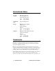
International Sales U.S. and Canada High End Systems, Inc. 2217 West Braker Lane Austin, TX 78758 USA voice: (512) 836-2242 FAX: (512) 837-5290 World Wide Web http://www.highend.com Europe High End Systems GmbH Lohstrasse 22 D-85445 Schwaig Germany voice: +49 8122 9903-0 FAX: +49 8122 9903-33 Singapore High End Systems Singapore Pte. Ltd.
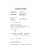
Declaration of Conformity according to ISO/IEC Guide 22 and EN45104 Manufacturer’s name: Manufacturer’s address: Distributor’s name: Distributor’s address: Declares that the product Product Name: Product Number: Product Options: Lightwave Research 2217 West Braker Lane Austin, Texas 78758 U.S.A. High End Systems Inc. 2217 West Braker Lane Austin, Texas 78758 U.S.A.
Important Safety Information INSTRUCTIONS PERTAINING TO CONTINUED PROTECTION AGAINST FIRE, ELECTRIC SHOCK, AND INJURY TO PERSONS ARE FOUND IN APPENDIX D. READ ALL CAUTIONS AND WARNINGS PRIOR TO ASSEMBLY, MOUNTING, AND OPERATING THIS EQUIPMENT. IMPORTANT: INFORMATIONS DE SÉCURITÉ INSTRUCTIONS RELATIVES À UNE PROTECTION CONTINUE CONTRE L' INCENDIE, LE CHOC ÉLECTRIQUE, ET CONTRE DES BLESSURES POSSIBLES SUR DES INDIVIDUS SE TROUVENT DANS L'APPENDICE D.
Warranty and Conditions Unpacking and Saving the Shipping Materials Do not discard the shipping carton and packing materials. The carton and packing materials are specifically designed to protect the product during transport. High End Systems assumes no responsibility for products damaged during transport. Therefore, you should return a product for repair in its original shipping carton and packing materials.
Limited Warranty Unless otherwise stated, your product is covered by a two year parts and labor limited warranty. It is the owner’s responsibility to furnish receipts or invoices for verification of purchase, date, and dealer or distributor. If purchase date cannot be provided, date of manufacture will be used to determine warranty period.
Freight All shipping will be paid by the purchaser. Items under warranty shall have return shipping paid by the manufacturer only in the Continental United States. Under no circumstances will freight collect shipments be accepted. Prepaid shipping does not include rush expediting such as air freight. Air freight can be sent customer collect in the Continental United States. REPAIR OR REPLACEMENT AS PROVIDED FOR UNDER THIS WARRANTY IS THE EXCLUSIVE REMEDY OF THE CONSUMER. HIGH END SYSTEMS, INC.
viii Studio Color LCD Controller
Table Of Contents Introduction Features........................................................................ intro-1 About This Manual ...................................................... intro-4 Note, Caution, Warning Symbols................................ intro-5 Getting Help................................................................. intro-6 Chapter 1 Preparing to Use Your LCD Controller Unpacking Your Controller ............................................... 1-2 Specifications...........
Chapter 4 Basic Programming Programming Overview .................................................... 4-2 Preparing to Program ........................................................ 4-3 Programming Guided Tour ............................................... 4-4 Creating a Program.......................................................... 4-10 Page Copy ....................................................................... 4-13 Creating a Loop..............................................................
Chapter 6 Advanced Programming Intended Audience ............................................................. 6-2 Using Position Presets ....................................................... 6-3 Address (Fixture) Parameter Copy .................................... 6-5 User Key Macros ............................................................... 6-9 Analog Inputs Ports ......................................................... 6-15 Remote Page Access.....................................................
Table Of Figures Figure 1-1. Location of the controller’s voltage selection switch and fuse. ................................................... 1-8 Figure 2-1. Connectors on the controller’s rear panel. .......... 2-2 Figure 2-2. The controller’s Addr(ess) menu is at the top level in the Studio Color menu system. .............. 2-9 Figure 2-3. The fixture’s Info menu displays information about the fixture, including the’s current firmware version. ..............................................
Figure 2-17. Locations of the other connectors on the controller’s rear panel........................................ 2-23 Figure 2-18. Locations of the power key switch, the key and Standby LED..................... 2-27 Figure 3-1. First of two drawings showing the LCD controller’s front panel. .......................................3-5 Figure 3-2. Second of two drawings showing groups of keys on the Studio Color LCD controller’s front panel. ......................................................
Figure 7-1. Slide the write-protect bar to the right to allow the RAM card to accept data, or move it to the left to prevent it from accepting data. .................................................. 7-11 Table of Tables Table 1-1. Studio Color Optional Accessories ....................... 1-6 Table 2-1. XLR Cable Pinouts .............................................. 2-15 Table 3-1. Primary and Complementary Colors ................... 3-12 Table 3-2. MSpeed Movement Times ..................................
xv Table of Tables Studio Color LCD Controller
Introduction Congratulations on your purchase of the Lightwave Research® Liquid Crystal Display (LCD) controller for the Studio Color™ Automated Wash Luminaire. The Studio Color LCD controller provides designers and operators with the means to control the Studio Color family of luminaires quickly and powerfully. Your microprocessor-based Studio Color fixture responds to an extensive set of programming commands called constructs.
• 891 pages (scenes) • 9 memories • Up to 1024 programmable presets from the front panel through the use of preset banking. • Up to 1023 programmable presets using an analog controller, such as the Touch Dimmer Twelve manufactured by High End Systems, Inc.
• Shutter strobing • Color mixing • Flip • Frost effect • Wide angle effect Playback: • Supports the MIDI Show Control “Go” command • Remote page and preset access • Audio advance: page advance, page halt, color modulate, dim modulate • Remote enable • One-touch preset playback of pages or loops • Variable-speed page advance • Random advance • Automatic all-memory playback (all programmed pages) Other: • PC Card Type 1 adapter slot for backup and transfer of programs and operating
About This Manual This manual provides easy-to-follow procedures for setting up and using your Studio Color LCD controller. It includes seven chapters and four appendices. First-time users should begin this manual with Chapter 1. Chapter 1: Preparing to Use Your LCD Controller — unpacking your controller and setting the voltage, if required.
Appendix A: Binary Access Table — listing of preset numbers (1 through 1023), preset keys, preset levels and analog-to-binary conversions. Appendix B: Construct Parameters — lists all constructs supported by the Studio Color LCD controller, their allowable parameters values and default values. Appendix C: Pinouts and Wiring Diagrams — diagrams of connector pinouts and wiring diagrams for experienced, technical users.
Getting Help U.S. and Canada From 8 a.m. to 6 p.m. (U.S. Central time) Monday through Friday: (800) 890-8989 24-hour FAX: (512) 834-9195 24-hour voice mail: (512) 837-3063 or (800) 890-8989 24-hour World Wide Web site http://www.highend.
Chapter 1 Preparing to Use Your LCD Controller 1 Unpacking Your Controller ............................................... 1-2 Save the Shipping Materials.........................................1-2 Inspecting the Contents ................................................1-2 Specifications..................................................................... 1-3 Model and Part Numbers .............................................1-3 Physical Specifications.................................................
Unpacking Your Controller First, unpack your controller and verify that it arrived complete and without any damage. Save the Shipping Materials Do not discard the shipping carton and packing materials. The carton and packing materials are specifically designed to protect the product during transport. High End Systems, Inc. assumes no responsibility for products damaged during transport. Therefore, you should return a product for repair in its original shipping carton and packing materials.
Specifications This section lists specifications for your Studio Color LCD controller. Model and Part Numbers • Model: Studio Color LCD Controller • Manufacturer: Lightwave Research 2217 West Braker Lane Austin, Texas 78758 U.S.A. U.S.A. • Distributor: High End Systems, Inc. 2217 West Braker Lane Austin, Texas 78758 U.S.A. • Product Number: Studio Color LCD Controller Physical Specifications • Controller weight: 21 lbs, 9.5 kg • Dimensions: cm: 17.78 H x 48.29 W x 26.85 D in: 7.00 H x 19.
Class 1 equipment-For continued protection against electric shock, connect this equipment to a grounded power source only. Use in dry locations only. RAM Card 256KB Static Random-Access Memory (SRAM), Type 1 PC Card (nee PCMCIA adapter). (You can use a larger-capacity PC Card, but the controller utilizes only 256KB.) One PC Card of this type is shipped with the controller. You can obtain additional/replacement adapters from your High End Systems dealer/distributor (part number 80440017).
Cables and Connectors • DMX data cables: Belden® 9841 or equivalent (meets specifications for EIA RS-485 applications) with characteristics listed below: • • • • • • 2-conductor twisted pair plus a shield maximum capacitance between conductors - 30 pF/ ft. maximum capacitance between conductor and shield - 55 pF/ft. maximum resistance of 20 W/1000 ft.
Optional Accessories Table 1-1 below shows the optional accessories for the Studio Color LCD controller available from your High End Systems dealer/distributor: Table 1-1.
Setting the Controller Voltage At the time of this writing, the Studio Color LCD controller is shipped from the factory set to 230V. Carefully examine the controller’s voltage setting (as shown in Figure 1-1 on page 1-9), then follow the instructions in this section if you need to change it. Warnings (1) Check the voltage selection switch before proceeding with the equipment setup! Be sure to match the voltage selection switch to your power source prior to operating this equipment.
Set or Verify Controller Voltage To change or verify the controller’s input voltage setting, locate the voltage selection switch on the rear panels shown in Figure 1-1 on page 1-9. 115 volts – This setting should be used for power supplies rated from 90V to 127V. Slide the switch so that “115” appears inside the switch opening. You must also do both of the following: • Change the controller’s fuse as shown in the section titled “Replacing the Fuse” on page 1-9.
1 L R DAT A LINK OUT ANALOG INPUTS B 1 234 1 2 3 45 6 78 1 234 1 2 3 45 6 78 SERIAL PORT RS-232 IN OUT 1-6 MASTE R SLAVE 7-12 REMOTE ENABLE S TE RE O A UD IO INP UT CAUTION FUS E voltage select 115 MID I PERSONA LIT Y A 115 V 0.5 A, SLOW BLOW 230 V 0.315 A, SLOW BLOW CAUTION voltage select 230V FUSE Figure 1-1. Location of the controller’s voltage selection switch and fuse.
Power Cord Cap If you wish to attach the controller to a 230VAC outlet, you must replace the molded power cord cap provided with the controller with another suitable type of power cord cap. The type of power cord cap you must obtain depends on the location in which the controller will be used. Note Because of the wide variety of power cord caps used worldwide, High End Systems, Inc. cannot make specific recommendations for the particular power cord cap you should use.
• The core which is colored brown must be connected to the terminal which is marked with the letter “L” or colored red. Class 1 equipment: THIS EQUIPMENT MUST BE EARTHED. Vigtig Sikkerhedsinformation - DANMARK Advarsel: Beskyttelse mod elektrisk chock.
1-12 Power Cord Cap Studio Color LCD Controller
Chapter 2 Setting Up Your Controller Rear Panel Descriptions..................................................... 2-2 Setting the Switches........................................................... 2-4 Configuring Switch Block A........................................2-4 Configuring Switch Block B........................................2-4 All Switches OFF: Default Configuration........... 2-4 Switch B-1: Master or Slave................................ 2-4 Switch B-2: Time Base..............................
Rear Panel Descriptions Figure 2-1 shows the locations of the connectors on the rear panel of the Studio Color LCD controller. IMPORTANT SAFETY INFORMATION. SEE INSTRUCTION MANUAL BEFORE USE. WICHTIGE SICHERHEITSINFORMATIONEN. BEDIENUNGSANLEITUNG VOR GEBRAUCH LESEN! D'IMPORTANTE CONSIGNE DE SÉCURITÉ. VOYEZ LE MANUEL D'INSTRUCTION AVANT L'UTILISATION DE L'APPAREIL. WARNING T o reduce t he risk of f ire or electric shock, do not expose this device to rain or mois ture.
MIDI In/Out ports: Where MIDI signals enter and exit the controller using standard MIDI connections. The controller supports the MIDI Show Control “GO” command. For more information, see the section titled “MIDI In and Out Ports” on page 2-22. Master/Slave ports: Ports for interconnecting master and slave controllers. Use the master/slave feature to expand the system to more than 8 unique fixtures. For more information, see the section titled “Master and Slave Controllers” on page 2-20.
Setting the Switches The two blocks of Personality DIP (dual in-line package) switches located on the controller’s rear panel are labeled A and B. Configuring Switch Block A OFF PERSONALITY A B 1234 Switch block A is currently not used, and all four switches must be set to the OFF position. 1234 Configuring Switch Block B PERSONALITY A B 12 345 678 ON This section describes the functions of the eight switches in Personality switch block B.
You can set the controller to operate as either a master or a slave (there can be only one master controller per link). Your choice of master and slave controllers determines the following: • • The master controller determines the modes of playback for all controllers that are slaved to it. The master controller sets all standby, advance, and modulate settings. Only the master controller accepts commands from a lighting console, if any. Only one master controller is allowed per link.
Switch B-2: Time Base Switch B-2 sets the controller’s input voltage frequency at either 50 Hz or 60 Hz. This setting must match the input voltage frequency of your power source because the controller senses this frequency as part of its internal timing circuits. Switch B-2 Off (default) – the controller operates at 60 Hz Switch B-2 On – the controller operates at 50 Hz Caution Selecting the incorrect time base (frequency) will result in erratic program playback.
Switch B-5: Binary Preset Access Switch B-5 Off (default) – (Twelve-level preset access.) An analog controller accesses each of 8 presets on 12 independent levels for a total of 96 presets. You must also select preset level access by setting switch B-3 ON. Switch B-5 On – When switch B-5 is ON, an analog controller accesses the first 10 of the 12 analog input channels in binary combinations to provide remote access to 1023 presets. You must also select preset level access by setting switch B-3 ON.
Switch B-6 On – Independent Presets; the controller behaves as follows: • The master intensity recorded in each preset is ignored. Master intensities will remain as-is during preset playback. Slave controller master intensity is not affected or controlled by the master controller. Slave controllers will each accept independent master dim settings via Lightwave Show Control protocol. • Slaved controllers’ modulation effects respond to the audio input of each individual controller.
Connecting Fixtures The Studio Color LCD controller uses its native DMX 512 protocol (language) to control Studio Color fixtures. Configuring the Fixtures Before using the controller with Studio Color fixtures, you must do both of the following: • Verify each fixture is using firmware version 38c or later. • Select a fixture number for each fixture. Verifying the Firmware Version You can verify the firmware version using the fixture’s Info menu as described below: 1.
2. Use the and arrow buttons located to the right of the display to select Info, as shown below: Figure 2-3. The fixture’s Info menu displays information about the fixture, including the’s current firmware version. 3. Press the button to view the Info menu items, then use the and arrow buttons to select VER, as shown below: Figure 2-4. The controller’s Ver(sion) menu displays the current firmware version. 4. Press the button to view the firmware version.
• If the firmware version is above 38, you have three options: crossloading firmware from another fixture on the same DMX link, using the Studio Color Upload Module, or using Status Cue. Consult the Studio Color User’s Manual for details about crossloading. 2 Setting A Fixture Number You must assign a unique fixture number, from 1 through 8, to each Studio Color fixture you wish to respond independently to control commands.
1. Keep pressing the
However, the Studio Color fixture has several built-in random (or unsynchronized) effects which work randomly even if multiple fixtures are assigned the same fixture number. For more information, see the section titled “Programming Hints” on page 3-2. 4. Press the button to save the fixture number and continue with the section titled “Cables and Terminators” on page 2-14.
4. Press the button, then use the and arrow buttons to select ADDR as shown below: Figure 2-9. Configuring the fixture to be controlled by fixture numbers rather than DMX 512 addresses. 5. Press the button to save your selection, then keep pressing the
Constructing Cabling You should construct cables using shielded, two-conductor cable with a male 3-pin XLR connector at one end and a female 3-pin XLR connector on the other end. Pinouts for both male and female XLR connectors are shown in Figure 2-10. Negative Negative Shield Positive Female XLR connector Male XLR connector Figure 2-10. Properly-constructed data cable.
Terminators The last device on each link must have a 120 ohm, 1/4 watt (minimum) terminator attached to its Data Out connector. You can construct terminators by following the instructions in Figure 2-11: 2. Disassemble the connector. 12 0 Ω 1. Obtain a male XLR connector. 3. Solder a 120 ohm resistor, minimum of 1/4 watt, between pins 2 and 3. 4. Reassemble the connector. 5. Install the terminator in the Data Out port of the last device in the link. Figure 2-11. Constructing a data cable terminator.
• A serial data distributor must be used if either of the following is true: • • You wish to connect more than 32 fixtures to a controller or more than 32 master/slave controllers together. The end-to-end cable span (the total length of all cables) on any link exceeds 500 ft. (153 m). The serial data distributor regenerates and retimes the signal; failure to use it can result in data errors.
Because each fixture has a unique fixture number, each one responds to commands from the controller independently from the other fixtures. Since fewer than 32 Studio Color fixtures are attached to the controller and because no cable spans more than 500 ft. (153 m), a serial data distributor is not required. Example #2: Multiple controllers are linked together as masters and slaves. One link spans more than 500 ft (153 m).
be linked to a lighting console via its MIDI, RS-232C or analog ports. Only the master controller (not the slaves) can accept commands from the lighting console. The system shown in Figure 2-13 can support up to 24 independently-functioning Studio Color fixtures (8 for each of the three controllers). Also notice that fixtures are numbered non-sequentially. The Studio Color LCD controller recognizes fixtures numbered in any order you wish, as long as all fixtures are numbered between 1 and 8.
5. Connect other devices to the Studio Color fixtures as desired, using the instructions in the documentation provided with those devices. 6. Place a male 120 ohm terminator on the female Data Out connector of the last device in the link. The procedure for making a terminator can be found in the section titled “Terminators” on page 2-16. Master and Slave Controllers Each controller supports up to 8 unique fixtures (8 fixtures that can be programmed to operate independently of each other).
1. Set personality switch B-1 on the rear panel of each slaved controller to ON. Refer to Figure 2-1 on page 2-2 for the location of the switches. The Slave LED (located above the Power key switch) turns ON. 2. Connect a shielded, 2-conductor cable with a 6 mm (1/4 inch) tip/ring/sleeve connector on each end from the master controller's Master (out) connector located on the rear panel to the slave controller's Slave (in) connector. 3.
MIDI In and Out Ports The controller supports the MIDI Show Control (MSC) “GO” command, a subset of the MIDI (Musical Instrument Digital Interface) specification. Typically, MSC is used either to connect different types of controllers to each other (for example, Studio Color LCD controllers and Intellabeam® LCD controllers), or to connect a master controller to a lighting console. IMPORTANT SAFETY INFORMATION. SEE INSTRUCTION MANUAL BEFORE USE. WICHTIGE SICHERHEITSINFORMATIONEN.
Other Connectors This section describes how to connect cabling to the other connectors on the controller’s rear panel. Because these other connectors are used in conjunction with advanced functions described further in Chapters 6 and 7, only a brief explanation is found here. IMPORTANT SAFETY INFORMATION. SEE INSTRUCTION MANUAL BEFORE USE. WICHTIGE SICHERHEITSINFORMATIONEN. BEDIENUNGSANLEITUNG VOR GEBRAUCH LESEN! D'IMPORTANTE CONSIGNE DE SÉCURITÉ.
Remote Enable port: Use the Remote Enable signal to enable and disable the controller from a remote location. Connect a shielded 2-conductor cable with a 3.
Rack Mounting the Controller After configuring the controller and connecting cables as described earlier in this chapter, you can mount the Studio Color LCD controller in a standard 19-inch rack as described in this section. The Studio Color LCD controller is designed to mount into a standard 19-inch equipment rack as specified by the MILSTD-189 and ANSI/EIA RS-310-C-77 specifications. The unit occupies four standard rack spaces. 1. Insert the unit into the front of the equipment rack.
Powering On the Controller Before continuing, make sure you have done all of the following: 1. Selected the controller’s voltage and frequency as described in the section titled “Setting the Controller Voltage” on page 1-7. 2. Installed the correct fuse as described in the section titled “Replacing the Fuse” on page 1-9. 3. Configured the controller’s switches as described in the section titled “Setting the Switches” on page 2-4. 4.
3. Insert the controller power key into the controller’s front panel power key switch and turn the key clockwise. The location of the key switch is shown in Figure 2-18.
• If the contents of memory and the RAM card do not match, the message below is displayed. If you want to save your programming to the RAM card, you must use the backup instructions in Chapter 5. 6.
Chapter 3 Overview of Controller Operation Programming Hints............................................................ 3-2 Color to Control ...........................................................3-2 Beam Shaping ..............................................................3-3 Random and Synchronized Effects ..............................3-3 Random (Unsynchronized) Effects ...................... 3-3 Synchronized Color Changes ............................... 3-3 Front Panel Descriptions................
Programming Hints This section gives you a brief overview of some of the effects you can program using the Studio Color LCD controller. Color to Control The Studio Color fixture offers you a number of preprogrammed color effects to choose from. Except where noted, these options are covered in more detail in the section titled “Color Key” on page 3-15.
Beam Shaping The Lens 1 and Lens 2 constructs (corresponding to the two Studio Color effects wheels) control beam shaping. Each effects wheel has four positions (three effects plus open). The three effects positions include beam shaping plus one other effect, as described below: Lens 1 (see “Lens 1 Key” on page 3-11): • Beam shaping: A long, narrow beam rotates into a short, fat beam. • Wide angle: The “effect” position is wide angle—a large beam diameter with defined edges.
Front Panel Descriptions Figure 3-1 is the first of two drawings that show groups of keys on the controller’s front panel. Descriptions of these key groups follow the figure.
Address LED is ON to indicate a fixture corresponding to that fixture number has been programmed with its light gate (shutter) open. • In Preset mode, these keys correspond to eight programmable presets in each of the 128 preset banks. Each preset is capable of storing a single page or a loop of pages (up to 99 consecutive pages) for instant recall. A Preset LED is ON to indicate a stored preset. For more information, see the section titled “Preset Programming” on page 4-19.
RAM card slot: Insert a RAM card (Type 1, 256KB SRAM PC Card) into this slot to store a copy of the controller’s operating system, to install an updated version of the operating system, or to transfer programs into or out of the controller’s memory. For more information, see Chapter 7. Select/Record/Erase keys: • Select key: Use this key for programming, editing, and manual control of selected fixtures. For more information about programming, see Chapter 4.
Construct/Cursor/Page control keys Studio Color INTENSITY MEMORY PAGE construct cursor page USER ADDRESS 1 3 2 PRESET 5 6 1 2 3 4 5 6 4 8 7 STANDBY 7 slave Construct keys 8 ADVANCE home auto POWER level rate 3 audio MEMORY CARD select record erase LIGHTWAVE Home key Joystick Figure 3-2. Second of two drawings showing groups of keys on the Studio Color LCD controller’s front panel.
Construct keys: Allow you to program Studio Color fixtures. For more information, see the section titled “Using the Construct Keys” on page 3-8. home Home key: Pressing this key then pressing one or more Address keys closes the shutter and returns the selected fixtures’ wheels and motors to their default (home) positions. For more information, see the section titled “Homing Fixtures” on page 4-29. Joystick: Use the joystick to position the beams of selected fixtures during beam programming.
Gate Key Use this key to open or close the gates (shutters) of selected fixtures, or to select from 60 strobe speeds numbered 0 (slowest) to 59 (fastest). You can also select from 60 random (arbitrary, unsynchronized) strobe speeds from 0 (slowest) to 59 (fastest). If you have a single fixture selected, the fixture appears to “strobe” at arbitrary rates. If you have multiple fixtures selected, they all “strobe” at individual rates.
Selecting a particular color construct shows you the complementary color for that construct. For example, after selecting the Red construct, the LCD display appears as shown below ( means 100%): & '( ) * ) ) + , !"#$%% -#' The second line of the display, !"#$%% , indicates the following: • RED: the color construct you selected (the primary color). • (-CYAN): Red’s complementary color (cyan).
Lens 1 Key See also “Lens 2 Key” on page 3-16. The two Studio Color effects wheels are controlled by the Lens 1 and Lens 2 constructs. Each wheel has four positions (three effects plus open). The three effects positions include beam shaping plus one other effect. Construct values of 0 and 255 select the open position; the other positions are described below. Lens 1 has the following effects: • Beam shaping: A long, narrow beam rotates into a short, fat beam.
MSpeed Key (Can be referred to as “motor” or “movement” speed.) The MSpeed construct determines the total length of time a beam will require to move from one position to another. Two fixtures assigned the same MSpeed value on a page will arrive at their recorded positions (not necessarily the same position) at the same time when that page is played back.
Table 3-2. MSpeed Movement Times MSpeed Value Time (sec.) MSpeed Value Time (sec.) MSpeed value Time (sec.) 92 0.94 59 25.80 26 85.59 91 1.18 58 27.10 25 87.95 90 1.45 57 28.44 24 90.33 89 1.76 56 29.80 23 92.76 88 2.09 55 31.19 22 95.21 87 2.46 54 32.62 21 97.69 86 2.86 53 34.08 20 100.21 85 3.30 52 35.57 19 102.76 84 3.76 51 37.09 18 105.34 83 4.26 50 38.65 17 107.95 82 4.79 49 40.23 16 110.60 81 5.35 48 41.85 15 113.28 80 5.
Table 3-2. MSpeed Movement Times MSpeed Value Time (sec.) MSpeed Value Time (sec.) MSpeed value Time (sec.) 69 14.58 36 63.78 3 147.90 68 15.56 35 65.82 2 151.00 67 16.57 34 67.89 1 154.13 0 157.28 Xfade Key (Crossfade.) Crossfade affects only the following Studio Color fixture features: Dim, Lens 1, Lens 2 and color mixing. Xfade is the length of time required for a value change in one of the four Xfade constructs to complete. You can select a value for Xfade from 0.
Dim Key Use this key to set the beam intensity level for all selected fixture numbers, from 0 (full dark) to 99 (full bright). Note The transition time of this construct is set using the XFade construct. Color Key 3 Use this key to set the following: • Positions 1 through 6 on the color wheel. • Forward/reverse wheel spin speeds from 1 (slowest) through 16 (fastest). • Cycle speeds from 1 (slowest) through 16 (fastest).
The display below selects a color between the half-color combination 2 and 3 (3/4 CTO and Pink) and position 3: * /0/ , /0/ # 1$ $32 2 4 -#' See also “CSpeed” on page 3-21. The factory configuration of the color wheel is shown below: 2 ¾ CTO 3 Pink 1 Open 4 Magenta 6 Aqua 5 Red Figure 3-4. Factory configuration of the Studio Color fixed color wheel. Lens 2 Key See also “Lens 1 Key” on page 3-11.
Lens 2 has the following effects: • Beam shaping: A long, narrow beam rotates into a short, fat beam. Construct values between approximately 100 (39%) and 220 (86%) select beam shaping. (Values above about 220 or 86% move toward the open position.) • Frost: The “effect” position is frost—soft, undefined beam edges. Values between below approximately 100 (39%) select frost.
4. Press the key and use the Construct and arrow keys to select / . 5. Use the joystick to direct the beam at a reference point (wall, screen, or other surface). 6. Press the key, then use the Construct and arrow keys to select ) ) ' * as shown below: * ) / , / # ) ) ' * -#' 7. Press the key and use the Construct and arrow keys to select a value of 5 . 8.
Position Key (POS) Use this key to select one of 99 user-programmable position presets. (You do not need to press this key if you want to manually position the beam as described below.) Manual vs. Preset Positioning There are two ways to position the beam: manually using the joystick or automatically using preset positioning. Preset positioning allows you to store pan/tilt values in the pages of memory 9 for instant positioning.
suppose you have programmed all 99 pages of memory 9 as position presets. All 99 position presets are available for fixture number 1, all 99 position presets are available for fixture number 2, etc. Delay Key Use this key to set the amount of time you want the controller to pause on the current page in the loop before advancing to the next page in the loop.
CSpeed This option is accessible only through the menus. For more information on accessing menus, see the section titled “Setting CSpeed” on page 3-21. (Color change speed.) This option determines how fixed color wheel changes occur: at the fastest possible speed (at the beginning of beam movement), or at the speed set by the MSpeed construct (the color change completes at the same time as the beam reaches its destination).
4. You have the options shown below: * ) ;- , ;- # ( ) * -#' You can select either ) * (default; change occurs as quickly as possible) or ) * (change occurs smoothly over the MSpeed time value). Use the Construct and arrow keys to select an option, then press the key to save your selection for the fixture number(es).
Chapter 4 Basic Programming Programming Overview.......................................................................... 4-2 Page, Construct, Parameter, Loop ................................................... 4-2 Address and Preset Mode ................................................................ 4-2 Preparing to Program .............................................................................. 4-3 Programming Guided Tour .....................................................................
Programming Overview The Studio Color LCD controller has 9 separate memories, each containing 99 pages, for a total of 891 pages of program storage. You can think of the controller’s memory as being like a book. The book has 9 chapters (memories) and each chapter has 99 pages. Page, Construct, Parameter, Loop Each page (which can also be called a look or a scene) stores a unique combination of constructs (fixture features) and their parameters (values) which together form a particular look or effect.
Preparing to Program Before beginning any programming, make sure the controller appears as shown below: Address LED on LCD display shows Intensity, Memory, Page Studio Color INTENSITY MEMORY Intensity: 99 ADDRESS 1 2 3 4 5 6 7 8 Memory: x construct PRESET cursor PAGE 1 2 3 4 5 6 page STANDBY USER Page: x Standby LED off 7 slave 8 ADVANCE home auto POWER level rat e 4 audio MEMOR
Programming Guided Tour This section leads you step-by-step through creating a simple four-page program, playing back the program page-by-page, creating a loop and recording a preset. Only one fixture is required, although you can use more than one if you wish. Recording Page 1 1. Configure the controller and connect fixtures as described in Chapters 1 and 2. Power ON fixtures then power ON the controller if you have not already done so. Make sure the controller appears as shown in Figure 4-1 on page 4-3.
9. Press the key to save page 1. Notice that the Address LEDs of all fixture numbers you selected are now ON. This is because the shutters of these fixtures are open (you selected / for the Gate construct in Step 5.) Recording Page 2 You will create pages 2—4 of the sample program using the controller’s page copy feature, which copies constructs and parameters from one page to another. 1.
10. Use the joystick to position the beam in a different place of your choosing. 11. Press the key to save page 2. Recording Page 3 1. Press the
Manually Playing Back Pages 1 Through 4 1. Use the Page and arrow keys to select page 1, as shown below: 7 # 88 # + - * # + 2. The fixture(s) programmed for page 1 should now display the color and position you selected for them. 3. Press the Page arrow key to select page 2. The fixture(s) programmed for page 2 should now display the color and position you selected for them. Do the same for pages 3 and 4.
3. Press the key. The LCD display appears as shown below: - ; ) = # + -# % ; 0 : ' 4. Press the key to un-initialize page 5. 5. Use the Page key to select page 1. 6. Press the key, located to the right of the joystick. 7. The pages in the loop begin playing back as you recorded them. The length of time each page “plays” is set by the Delay construct.
3. Press the numbered Preset key where you want to record the preset. For example, to record preset number 1, press the <1> key. Note The Studio Color LCD controller supports up to 1024 presets from the front panel through the use of preset banking. In this simple procedure you do not need to use it, but if you would like to learn more, see the section titled “Preset Programming” on page 4-19. 4. Press . You are finished recording the preset.
Creating a Program This section gives you detailed step-by-step instructions for creating a program. For a quick step-by-step overview, see the section titled “Programming Guided Tour” on page 4-4. Figure 4-2 below shows the programming keys that will be referenced in this section.
Step 3: Press the Select Key Press the
Step 6: Press the Record Key When you are finished editing constructs, press the key to save your page. Note After recording the page, the address LEDs of all fixture numbers with the Gate construct set to / come ON. If the Gate construct is set to ) , the address LED will not be on, regardless of the other construct parameter values. Where To Go From Here After programming your first page, you can do the following: • Program additional pages the same way.
Page Copy Use page copy to copy the entire contents of a programmed page to any other page in any other memory. This is useful for creating additional pages that contain only slight changes, such as movement changes or single-parameter changes. Before continuing, make sure your controller is ready for programming as shown in Figure 4-1 on page 4-3. Also, make sure you have programmed at least one page. 1. Select the page (source) that you want to copy from using the Page and arrow keys. 2.
Creating a Loop A loop is a sequence of pages that repeats continuously until you stop it. You can vary the rate of playback using the knob. You must perform the two basic steps shown below: Step 1. Record the pages as a contiguous block in the same memory. For example, memory 1, pages 1—10. Step 2. Designate un-initialized pages that “bracket” (one before and one after) the pages in the loop.
You can record over an un-initialized page with a programmed page at any time. Note The controller automatically places an un-initialized “page” between pages 99 and 1, as shown in Figure 4-4. So if the first page of your loop is page 1, you need to create one un-initialized page after the last page of your loop. If the last page of your loop is page 99, you need to create one un-initialized page before the first page of your loop.
3. Press the key. The LCD display appears as shown below: - ; ) = # ' -# ' ; 0 : ' 4. Press the key again to un-initialize the page. 5. Repeat steps 1 to 4 for the second or ending un-initialized page. (If the last page of your loop is 99, an ending page is not needed.) Block Copy (and Reverse) Before continuing, make sure your controller is ready for programming as shown in Figure 4-1 on page 4-3.
3. Press the key, located to the right of the joystick. The LCD display then appears similar to the one shown below: /- # + -# + #> -#> #> -#> 4. Select the memory and first page of the block of pages you want to copy from. • Press the Cursor and arrow keys to change the memory number. • Press the Page and arrow keys to change the page number. 5. Press the key.
Setting Rate and Delay Time Before continuing, make sure the controller is ready for programming as shown in Figure 4-1 on page 4-3. You can control the speed of your loop using the knob and the Delay construct. The Delay construct (also called delay time) determines how long each page in the loop “plays” before moving on to the next page, and the knob lengthens or shortens the delay time.
Varying the Delay Time The Delay (time) construct sets the amount of time you want the controller to pause on the current page before advancing to the next page. Turning the knob clockwise subtracts from the delay time; turning the knob counter-clockwise adds to the delay time. Note Audio advance causes the controller to ignore the Delay and Rate settings. For more information, see the section titled “Audio Input Playback” on page 6-27.
Notes (1) Audio advance is independent of the presets. For more information about audio triggering, see the section titled “Audio Input Playback” on page 6-27. (2) To prevent inadvertent erasure of presets, you cannot directly erase pages used as presets. You record over existing presets to change them.
Recording a One-Page Preset ADDRESS PRESET 1. Use the Construct and Page and arrow keys to select the memory and page you want to record as a preset. 2. Toggle the / key until the Preset LED turns ON. The LCD display then appears as shown below: 7 # 88 # + & ,? # + + @" - * # + 3. Use the Cursor and arrow keys to select a bank of presets. Each bank contains 8 presets. 4.
Recording a Loop as a Preset Start the loop running, then assign the entire loop to one of the Preset keys. For more information about loops, see the section titled “Creating a Loop” on page 4-14. ADDRESS PRESET 1. Use the Page and arrow keys to select any page within the loop that you want to record as a preset. 2. Toggle the / key until the Address LED is ON. 3. Press the key.
• Advance settings: • • • Random, Audio 1, Audio 2: see “Audio Input Playback” on page 6-27. Auto: see “Setting Rate and Delay Time” on page 4-18. Effects settings: Color modulate and Intensity (dim) modulate. See “Audio Input Playback” on page 6-27. 10. Press the key. You are now finished. Preset Playback 4 You can play back presets in the following ways: • Pressing one of the numbered Preset keys on the controller’s front panel.
Things to Remember • To change to another preset at any time, switch to the bank containing the preset and press the corresponding Preset key. • If a preset is playing back a loop, you can quit playback by pressing the key until the Auto LED turns OFF. The currently-running preset stops at the page that is active when you press the / key.
Viewing and Editing Programs Once your pages are programmed, you can view or edit the pages you programmed and change any constructs or parameters you wish. Use the same procedure you used to record the pages, making sure you press when you are finished editing. See the section titled “Creating a Program” on page 4-10. Viewing Fixtures You can quickly view the current constructs and parameters of a particular fixture number by pressing and holding the Address key. 1.
4. A summary of all constructs and parameters for that fixture number appears, similar to the one shown below: ) 9 ?) 0+ 0$ ; - C( ) - * 88 + 5 5 88 B; 5 + 5 5 + Most fields are self-explanatory; below is a brief description of some of the fields: • • ; : Displays the MSpeed setting. - : (Beam position.) B;< as shown above, indicates the beam has been positioned manually using the joystick.
Erasing Pages You may want to erase a page when there are undesirable or old pages in memory. It is often best to clear out these pages to prevent confusion in future programming. Note the following: • Instead of erasing the page, you could always record another page in its place. • Erasing a page causes that page to become a “blackout” page (the Gate construct is set to “Closed”, so all fixtures go dark). • An erased page is still an initialized page. 1.
Master Dim The sample LCD display below shows a value of 88 for Intensity (also called master dim). The value of 99 is maximum intensity (full bright) and 0 is the minimum intensity (full dim). 7 # 88 # ' - * # ' You can change the intensity setting using the Construct and arrow keys. Master dim can also be controlled in the following ways: • By a submaster as described in the section titled “Submasters” on page 6-23.
Homing Fixtures Homing a fixture causes its shutter to close, its lamp to strike (if off), and for all wheels and motors to return to their home (default) positions. 1. At any time, press the key on the controller’s front panel. The LED flashes. 2. While the LED is flashing, press the Address key(s) corresponding to the fixture(s) you want to home. 3. The Home and selected Address LEDs now flash for another 10 seconds and the fixtures perform their homing operations.
4-30 Homing Fixtures Studio Color LCD Controller
Chapter 5 Using the Menus Overview............................................................................ 5-2 Navigating the Menus........................................................ 5-4 Summary ......................................................................5-4 Getting Started .............................................................5-4 Menu Movement Keys.................................................5-5 Moving Through Menu Levels ....................................
Overview Figure 5-1 shows an overall view of the menu system: Help Help Edit Backup Submasters Setup Backup Submasters Mem Card Card Mem O/S Card Master (No channel; 1 to 12) 1 (1 to 8) (Dim, Color) 2 (1 to 8) (Dim, Color) 3 (1 to 8) (Dim, Color) 4 (1 to 8) (Dim, Color) 5 (1 to 8) (Dim, Color) 6 (1 to 8) (Dim, Color) 7 (1 to 8) (Dim, Color) 8 (1 to 8) (Dim, Color) 9 (1 to 8) (Dim, Color) 10 (1 to 8) (Dim, Color) 11 (1 to 8) (Dim, Color) 12 (1 to 8) (Dim, Color)
• Help: On-screen help for all Main menu options. • Backup: Options for transferring controller memory to and from a RAM card and for backing up the controller’s operating system to a RAM card. See Chapter 7. • Submasters: Allow you to change color and dim constructs remotely using a 0—10V analog controller. See the section titled “Submasters” on page 6-23. • Setup: Set the following options: • • • • • • • Device-ID: Select the controller’s Device ID.
Navigating the Menus This section explains how to use the menu system. More information is contained in subsequent sections in this chapter. Summary • Press the
the Main menu. 6 0- ( - D ( ) You use the Construct, Cursor and Page arrow keys to navigate in the menu system. These keys are shown in Figure 5-2: construct cursor page 5 Figure 5-2. The menu navigational keys: Construct, Cursor and Page. Menu Movement Keys The Cursor and arrow keys move side-to-side to select menu options. A selected menu option appears in ALL CAPS.
below: , , 3 , - / Pressing the Cursor arrow key again has no effect, since there are no menu items below , . Pressing the Cursor and arrow keys select different menu options on the same level, and pressing the Cursor arrow key returns you to the Main menu. Selecting Options Usually the Construct and arrow keys are used to select options for the lowest-level menu items.
Multi-Page Menus Some of the Help menus are more than one page long. You use the Construct and arrow keys to scroll through those multi-page menus. Select 6 ) from the main menu, then press the Cursor arrow key to select the first option, 6 ) .
Selecting MSC or LSC MIDI Show Control (MSC) and Lightwave Show Control (LSC) are two different protocols (languages) that achieve the same effect: coordinating and controlling playback of master controllers. (MSC and LSC have no effect on slaved controllers, since playback of slaved controllers is determined by masters.) These protocols allow you to set up cue lists to determine the order in which your programmed presets or pages are played back.
3. Press the Cursor arrow key to display the menu options shown below: E7 G7 G) ) 3 , 7 A 5 4. Use the Cursor and arrow keys to select ; ) , as shown below: G G) ; 7 0 -/ : 3 , ; $2$ ( 0 * D ) 5. Press the Construct and arrow keys to change the selection between 7 7 ; D ) 9/ or ; $2$ ( 0 * D ) . 5 6.
If you are continuing from the previous section, begin with Step 3. 1. Enter the menu system by pressing the
All-Memory Playback This section describes how to auto advance or random advance through all 99 pages in all nine memories. (Only initialized, or programmed, pages will play back.) Enabling All-Memory Playback Make sure the controller is ready for programming as shown in Figure 4-1 on page 4-3.
Locking/Unlocking Memory Use the memory lock function to lock out all pages in a memory so they cannot be edited or erased without the memory first being unlocked. Locking a memory also prevents editing of any preset referring to any page in that memory. 1. Enter the menu system by pressing the
Locking/Unlocking a Fixture This feature temporarily removes a fixture from all pages. This might be necessary in the event of a fixture malfunction or if you want to remove a fixture for a special event or effect. Removing a fixture in this manner requires no reprogramming because no memory is actually changed. Use the same procedure to return the fixture to normal operation. Locked fixtures are unlocked at controller powerup as well. 1.
Erasing All Memory The Erase All function provides a quick way to clear all programming (all unlocked memories, all pages, all presets). This operation does not affect any locked memories, the controller’s operating system, User key macros, menu choices (for example, device ID) or submasters. Note You may want to temporarily back up the controller before you perform this operation. For more information, see Chapter 7. 1. Enter the menu system by pressing the
Setting the Backlight Intensity You can set the intensity (brightness) of the LCD display backlight to high (the default), low, or off. 1. Enter the menu system by pressing the
5-16 Setting the Backlight Intensity Studio Color LCD Controller
Chapter 6 Advanced Programming Who Should Use this Chapter............................................ 6-2 Using Position Presets ....................................................... 6-3 Recording Position Presets...........................................6-4 Recalling Position Presets ............................................6-4 Address Parameter Copy ................................................... 6-5 Edit/Copy .....................................................................
Who Should Use this Chapter This chapter is intended for users already familiar with controller operation and with the basics of programming. In many cases, details such as how to enter or exit the controller’s menu system have been omitted.
Using Position Presets The controller has a time-saving feature called position preset (also called position memory or preset positioning). Position presets allow one page to refer to another page for pan and tilt (position) information. You first move the beam to the desired location using the joystick, then assign that position to a preset number (from 1 to 99). You can recall the same position preset in other pages.
The full set of 99 position presets is available for all fixtures connected to the controller. For example, suppose you have programmed all 99 pages of memory 9 as position presets. All 99 position presets are available for fixture number 1, all 99 position presets are available for fixture number 2, etc. Recording Position Presets 1. Use the Cursor and arrow keys to select memory 9, then use the Page and arrow keys to select a page.
4. Press the (Position) construct key and use the Construct and arrow keys to select a position preset. (A value of B/ ;:7 H indicates you are using manual positioning, not preset positioning.) For example, the LCD display below selects position preset 1 (memory 9, page 1): & -/;7:7/! '( , -/;7:7/!# - ; : + -#+ 5.
Edit/Copy The Edit/Copy feature has two options: • “Share all Constructs until selected” (the default): Copies all of a fixture’s construct parameters to the fixture(s) you have selected to “copy to”. You can override this by pressing one or more Construct key(s) to copy only those constructs. • “Don’t share constructs until selected”: You must select the particular construct(s) you do want to copy by pressing the appropriate Construct key(s) until the LED indicator above that key lights.
Copy Parameters to Another Fixture, Same Page 1. Select the memory and page containing the fixture with the parameters you wish to copy. 2. Press the
Copy Parameters From One Page to Another Page 1. Select the memory and page containing the fixture with the parameters you wish to copy. 2. Press the
User Key Macros The controller has eight front panel User keys that can be used to store custom macros (a recorded series of up to 256 keystrokes); five of the first six keys have pre-programmed definitions that you can use or record over. (You can access the default definitions even after you record over the keys.
3. The selected User key’s LED flashes, indicating you are recording. Every keystroke you make from now on is recorded in this macro. The macro accepts up to 256 keystrokes. See the example below. 4. When you have completed your macro, repeat Step 1 then select ; from the menu. Example Macro: Page Copy This macro copies the entire contents of the page the controller is currently set on to another page. 1. Select a memory and page to copy from using the Cursor and Page and arrow keys.
6. Select the memory and page (destination) you want to copy the contents of the current page to: • Press the Cursor and arrow keys to change the memory number. • Press the Page and arrow keys to change the page number. Note Make sure the page you select does not already contain a program, because the page would be erased. 7. When you press the Cursor or Page key for the first time, the LCD display shows the source memory and page fields.
Erasing a Single User Key To erase one of the User keys, record a zero-keystroke macro over the old macro using the instructions in this section. Note Erasing an individual User key does not return it to its default definition. However, you can restore all six User keys to their default definitions as shown in the section titled “Erasing All User Keys” on page 6-14. 1. Press and hold the User key you wish to erase until appears on the LCD display, then release the key.
Accessing Default Definitions This section describes how to access the six default User key definitions after any or all of these keys have been redefined as macros. Note You can restore all six User keys to their original preprogrammed state by erasing all User keys. See the section titled “Erasing All User Keys” on page 6-14. 1. Select from the Main menu, then press the Cursor arrow key. 2.
Erasing All User Keys Erasing all User keys deletes any custom macros you have programmed and returns the eight User keys to their default definitions. (Memories, pages, presets, submasters, menu choices and the controller’s operating system are not affected.) For more information about User keys, see the section titled “User Key Macros” on page 6-9. 1. Select ; from the Main menu, as shown below: ) ; : - ( - D ( ( 2.
Analog Inputs Ports You can attach an analog controller to the two Analog Inputs ports located on the Studio Color LCD controller’s rear panel to perform any of the following functions: • Remote page access: Remotely play back pages from the memory. For more information, see “Remote Page Access” on page 6-16. Set switch B-3 on the Studio Color LCD controller’s rear panel to OFF. • Remote preset access: Remotely record and play back presets using either twelve-level preset access or binary preset access.
Remote Page Access The remote page access feature allows you to remotely play back pages from the memory that you first select on the controller’s front panel. (You cannot remotely select or change memories.) 1. Connect the analog controller as described in the section titled “Analog Inputs Ports” on page 6-15. Set switch B-3 on the Studio Color LCD controller’s rear panel to OFF. 2. Select the memory containing the pages you want to remotely access using the Cursor and arrow keys. 3.
c. Channels 10, 11, and 12 when used in combination with other channels become function keys as explained below: • Channel 10 is a ten-times multiplier. For example, if you simultaneously enable channels 5 and 10, you call up page 50. • Channel 11 is an eleven-times multiplier. For example, if you simultaneously enable channels 2 and 11, you call up page 22. • Channel 12 is a number inverter. For example, if you simultaneously enable channels 2, 4, and 12, you call up page 42 rather than page 24.
Remote Preset Access Twelve-level preset access and binary preset access allow you to do one or both of the following: • Play back individual pages or loops (even individual pages within loops). • Play back the same loop with different settings for: auto advance, audio 1 and 2 advance, random advance, color modulate or dim modulate. More detail about each kind of preset access is shown below: • Twelve-level preset access: Record and play back up to 96 presets (eight presets for each of 12 channels).
Using Twelve-Level Preset Access Twelve-level preset access allows you to record and play back up to 96 presets (12 sets or levels of eight presets each). Recording in Twelve-Level Preset Access 1. Toggle the
/ key on the Studio Color LCD controller until the Preset LED comes ON. 2. Press the Page and arrow keys on the Studio Color LCD controller to select the page that you want to record as a preset. If you want to record a loop as a preset, select any page within the loop. 3.audio 1 and 2 advance (page 6-27), color modulate (page 6-27) and dim modulate (page 6-27) as needed. These settings are stored with the preset. 9. Press the key. The Select LED stops flashing, indicating the preset is now recorded. Note If enabling analog controller channels does not call up presets in memory, make sure there are no submasters assigned. See the section titled “Submasters” on page 6-23. Playing Back in Twelve-Level Preset Access 1.
Using Binary Preset Access Binary preset access allows you to record and play back up to 1023 presets (the first 10 analog controller channels act as binary digits). The controller supports mixing binary presets with submasters; however, the same channel cannot serve as both a submaster and a preset at the same time. The submaster takes precedence over the preset.
auto advance (page 4-18), audio 1 and 2 advance (page 6-27), color modulate (page 6-27), and dim modulate (page 6-27) as needed. These settings are stored with the preset. 6. Convert the preset number you wish to use to a binary number using Appendix A. Then enable all analog controller channels corresponding to binary 1s and disable controller channels corresponding to binary 0s. 0V = Disabled 5V-10V = Enabled Examples: • Preset 1: preset 1 in binary is 1000000000.
Playing Back in Binary Preset Access Appendix A lists all of the binary preset access combinations.
Selecting a Submaster Mode There are two submaster modes: Proportional level or Remote level. • Proportional Level submasters (typical setting): Traditional submaster control. The submaster value is multiplied by the programmed fixture value. For example, if the recorded dim value for the selected fixture is at 50 percent and a submaster is at 50 percent, the fixture will be dimmed at 25 percent. If there are two or more submasters, the submaster with the higher setting has control.
Assigning a Channel for Master Dim This section explains how to use a submaster as the “master dim controller”. Once you assign a channel for master dim, the same channel cannot be used to control fixtures. For example, if you select channel 1 for master dim, you cannot use channel 1 to control fixtures. Note When the master dim is assigned to a channel, you should not use the Studio Color LCD controller for master dim control; master dim should be controlled by the submaster “master dim controller”. 1.
You can skip the first two steps below if you are continuing from the previous section. 1. Select ; from the Main menu, as shown below: ) ; ? ;: ; ( - D ( ( 2. The LCD display then appears similar to the one shown below: 1 ;: 4 + $ 2 . % J K @ 8 +5 ++ +$ / ! ) * 3. Use the Cursor and arrow keys to select the submaster number as shown below (submaster 1): 1+4 $ 2 .
Audio Input Playback You can use an external stereo source to control playback through any or all four playback modes listed below. Audio input playback affects how initialized pages play back, regardless of whether those pages are part of a loop or not. To enable audio input playback, plug your stereo source into the Stereo Audio Input connector on the controller’s rear panel as shown in the section titled “Other Connectors” on page 2-23. Also see the section titled “Random Advance” on page 6-29.
Varying the Audio Sensitivity Adjust the sensitivity of the audio advance modes to the audio signal using the
Random Advance Random advance when used with auto advance, manual advance or audio advance (and optionally all-memory playback) plays initialized pages in random order. (Random advance when enabled by itself does nothing.) First press the key, then enable random advance. By default, the User <1> key is defined as random advance. If you have already programmed a macro on the User <1> key, see the section titled “Accessing Default Definitions” on page 6-13.
3. To return from “live” control press the
Lightwave Control Center Selecting Lightwave Show Control (LSC) as described in the section titled “Selecting MSC or LSC” on page 5-8 means you must use the Lightwave Control Center (LCC) software for playback control using binary preset access. (The eight preset keys on the controller’s front panel are not used with binary preset access.) LCC allows you to set up cue lists so you can access your 1023 presets in any order. Note LCC must be used in conjunction with binary preset access.
6-32 Lightwave Control Center Studio Color LCD Controller
Chapter 7 External Memory Storage and Transfer Overview ..................................................................................... 7-2 RAM Card Options ............................................................... 7-2 Personal Computer Options .................................................. 7-3 NiCad Battery Protection...................................................... 7-3 RAM Card: Memory .................................................................. 7-4 Backing Up to a RAM Card ....
Overview This chapter describes options for backing up and restoring the controller’s internal memory and operating system. You have different options depending on whether you use a RAM card or a personal computer. You can also crossload memories, pages and presets directly from one controller to another controller. See the section titled “Crossloading” on page 7-30 for more information.
Personal Computer Options In addition to backing up and restoring controller memory using a RAM card, you can also back up (download) and restore (upload) memories, pages and presets using a personal computer. The differences between backing up and restoring memory via RAM card and personal computer are summarized below: • You cannot back up or restore the controller’s operating system using a personal computer.
RAM Card: Memory This section explains how to: • Copy all of the controller’s internal memory to a RAM card • Load or restore the controller’s memory from a RAM card See also: • “IBM-Compatible” on page 7-13 • “Macintosh” on page 7-24 • “Crossloading” on page 7-30 Note When you are not using a RAM card, you should write-protect it to avoid accidental data erasure. See the section titled “RAM Card: Write-Protection” on page 7-12.
2. Press the
6. If you want to cancel the backup operation at this time press the
3. Use the Cursor and arrow keys to select ? from the Main menu, as shown below: ) ? H - - D ( ) 4. Press the Cursor arrow key to view the menu items, then use the Cursor and arrow keys to select , , as shown below: , , 3 , - ; ) 5. Press the key to load the contents of the RAM card to the controller, or press the
RAM Card: O/S This section explains how to back up, replace or update the controller’s operating system from a RAM card. Note When you are not using a RAM card, you should write-protect it to avoid accidental data erasure. See the section titled “RAM Card: Write-Protection” on page 7-12. Backing Up the Operating System to a RAM Card Use this procedure to back up the contents of the controller’s operating system to a RAM card.
4.
Restoring the Operating System from a RAM Card This section describes how to install an operating system from a RAM card to the controller. You should use this procedure if you are installing an updated or replacement (same version) operating system. You can obtain updated operating systems from your High End Systems dealer/ distributor. 1. Turn OFF the controller. 2. Insert the RAM card with the newer or replacement (same) operating system version into the RAM card slot on the front panel.
7. Press the key again to continue, or press the
RAM Card: Write-Protection After backing up either the operating system or memory to the RAM card, you should write-protect that card to prevent it from being inadvertently erased. Examine the end of your RAM card to locate the small writeprotect tab. Also note the battery release, typically located near the battery compartment. Do not disengage the battery release, since that could cause the battery to fall out of the RAM card.
IBM-Compatible This section describes how to back up and restore the controller’s pages, memories and presets using an IBMcompatible personal computer. See also: • “RAM Card: Memory” on page 7-4 • “Crossloading” on page 7-30 • “Macintosh” on page 7-24 Hardware/Software Requirements Hard or floppy disk with at least 260KB of available space; one floppy drive (or two if you want to backup/restore to or from a floppy); an RS-232C serial communication port; and a standard serial communication cable.
DB9 to DB25 Adapter Male DB9 connector Female DB25 connector You can use a DB9 to DB25 adapter if the female end of your serial cable does not match your computer’s serial port. Make sure you do not use a null modem adapter, since that will prevent the controller from communicating with your computer. Connecting the Computer and Controller Figure 7-2 shows two different connections. The top diagram shows how to connect a PC with a DB9 serial port to the controller using a standard DB9-to-DB9 cable.
Initial Setup You must follow the procedure below backing up controller memory to a personal computer, or restoring pages, memories and presets from a personal computer to the controller. 1. Toggle the controller’s key until the Standby LED comes ON. 2. If you are currently running Windows, exit to a DOS prompt. 3. Insert the backup diskette shipped with the controller into your computer’s floppy diskette drive. Type one of the following commands, followed by : A:LWBACKUP B:LWBACKUP 4.
6. The menu shows the currently-selected option in reverse video; in Figure 7-3, the selected option is Help. 7. Use your computer’s and arrow keys to select Setup and press . 8. The Setup pop-up menu prompts you to select a COM (or serial communication port) for the backup program to use. Lightwave Research Backup, Ver. 2.0, Copyright 1992 Help Contro Currently using COM port 1 Compu Setup Press 1—4 to change COM port Exit or ESC for main menu. Press F1 at any time for help.
10. Now see one of the following sections: • “Backing Up (Downloading) Memory to the Computer” on page 7-17 • “Restoring (Uploading) Memory from Computer to Controller” on page 7-20 Backing Up (Downloading) Memory to the Computer Before following this procedure, you must have already followed the instructions in the following sections: • “Connecting the Computer and Controller” on page 7-14 • “Initial Setup” on page 7-15 1.
2. The next menu gives you the following options which are available throughout the rest of the procedure. Use your computer’s and arrow keys to select an option and press . • Current directory: the top of the menu displays the current drive and directory (by default, C:\). • >>>NEW FILE<<<: Create a new file to back up to. This file will be located in the current directory. • >>>CHANGE DRIVE<<<: Locate the backup file on a different hard or floppy drive.
6. Press and hold the key (about 10 seconds) on the controller’s front panel until the LCD display shows the following message: D ) ; $2$ - ; 77 ( ) < / 7. The Lightwave Research Backup menu should now display an identical message. • If so, press Y on your computer’s keyboard. • If not, you have not selected a file to store the backup. Repeat the previous steps. 8. The next menu shows which drive, directory and file you will back up to.
Verifying the Transfer Make sure the memory was backed up properly using either Windows File Manager (or Explorer) or the DOS dir command. The file should be about 256KB in size. If so, you are finished. If the file is smaller than 256KB, some problem occurred during the transfer. Follow the troubleshooting suggestions below: • If the file was larger than 0KB but less than 256KB, the most likely cause was that something interrupted the transfer.
1. Use your computer’s and arrow keys to select Computer->Controller from the Lightwave Research Backup main menu, as shown in Figure 7-6: Lightwave Research Backup, Ver. 2.0, Copyright 1992 Help Controller -> Computer Computer -> Controller Setup Exit Press F1 at any time for help. Figure 7-6. Restoring memory from a file stored on a computer to the controller. 2. The next menu gives you the following options which are available throughout the rest of the procedure.
3. First, select the drive where the backup file is located. The current drive is displayed at the top of the menu (by default, C:\). Use the options shown in Step 2 to change the drive, if necessary. 4. Now select a directory on the drive you selected in the previous step. Use the options shown in Step 2 to change the directory, if necessary. 5. Once you have selected a drive and directory, all files in the directory are displayed.
9. A message is displayed on the Lightwave Backup software menu when the transfer is complete. Press the controller’s
Macintosh This section describes how to back up and restore the controller’s pages, memories and presets using a Macintosh personal computer. See also: • “RAM Card: Memory” on page 7-4 • “IBM-Compatible” on page 7-13 • “Crossloading” on page 7-30 Hardware/Software Requirements Macintosh-to-Modem cable Male DB25 connector Hard or floppy drive with at least 260KB available space. • One Macintosh-to-modem cable (male DIN 8 connector on one end and a male DB25 connector on the other end).
3. Connect the Mac-to-modem cable to the DB25 end of the adapter. See Figure 7-7: Controller RS-232C port Modem/printer port DB25 (female) to DB9 (male) adapter Mac-to-modem cable Figure 7-7. Connecting a Macintosh to the controller for download/upload. Setting Up the Software You must follow the procedure in this section before either backing up controller memory to your computer, or restoring memory from the computer to the controller.
described in the section titled “Connecting the Computer and Controller” on page 7-24. 1. Start White Knight. Press Command+U to open the Serial Port Settings dialog box and set the serial port for all of the following: • Serial port type: Modem (click the telephone icon) • Baud rate: 9600 • Parity: Ignore • Databits: 8 • Stopbits: 1 • Duplex: Full 2. Click OK to accept the serial port settings. 3.
1. Toggle the key on the controller’s front panel until the Standby LED turns ON. 2. Press and hold the key on the controller’s front panel until the LCD display appears as shown below: D ) ; $2$ - ; 77 ( ) < / 3. Your computer screen should display the following message: Save from controller to PC. Set PC to receive, then press RECORD to begin. Press SELECT to quit anytime. 4.
Verifying the Transfer Open the Get Info window on the file you just captured to make sure the file is about 256KB in size. If the file was 256KB, you are finished. • If the file was larger than 0KB but less than 256KB, the most likely cause was that something interrupted the transfer. Check the cable connections on both ends, verify the cable or replace it with a known working cable.
2. Your computer screen should display the following message: Restore to controller from PC. Send data to controller now. Press SELECT to quit anytime. 3. Press Command+Y to send a text file. Use the Please Select A File dialog box to locate the file containing backed-up memory, then click Select to start the upload. 4.
If the pages are not programmed as you expected, first open the Get Info window on the backup file. If the file was less than 256KB in size, it did not contain all of the controller’s memories and pages. Check both of the following: • Check the cable connections on both ends, verify the cable or replace it with a known working cable. • Repeat the procedure, making sure not to press the
If you do not have a null modem cable, you will need the following (see Figure 7-8 on page 7-31): Serial Cable (Female DB9) (Male DB9) • One standard DB9 female-to-DB9 male serial cable. • One DB9 male-to-DB9 male null modem adapter, or both of the following: • One DB9 male-to-DB9 female null modem adapter • One DB9 male-to-DB9 male gender changer Note A gender changer looks exactly like a null modem adapter. It would be a good idea to label them so you don’t get them confused later.
Consult Appendix C for a complete selection of cabling and connector wiring diagrams. Crossload Procedure The source controller is the one you want to transfer data from; the destination controller is the one you want to transfer data to. 1. Toggle the keys on each controller until their Standby LEDs come ON. 2.
the amount of data you crossload. 5. The LCD display of the destination controller shows the following when the transfer is complete: ) ( ; $2$ * # 8 -# ** 6. Restart the destination controller. Verifying the Transfer Make sure the transfer was successful by checking the programming on several pages in different memories you know should have been changed. If the pages were programmed as you expected, you are finished.
7-34 Crossloading Studio Color LCD Controller
Glossary Access Modes The controller offers the following two remote access modes: • Page access: An attached analog controller accesses pages in memory. See Chapter 6 for more information. • Preset access: An attached analog controller access presets, either by 12-level preset access or binary preset access as described in Chapter 6. Address Mode ADDRESS PRESET A mode of the controller that allows you to directly access fixtures for programming pages.
All-Memory Playback When used with auto advance, allows you to play back all 99 pages in all nine memories. (Only initialized, or programmed, pages will play back.) If used with random advance, pages play back in random order. Beam Shaping A unique feature of the Studio Color fixture that allows you to align the beam horizontally or vertically. Beam shaping (along with one other special effect) is controlled by the Lens 1 and Lens 2 constructs; see Chapter 3 for more information.
Crossloading Transferring memories, pages and presets directly from one controller to another. Also refers to transferring firmware from one Studio Color fixture to other fixtures on the same DMX link. See Chapter 7 for more information about crossloading between controllers. See the Studio Color User Manual for information about crossloading firmware between fixtures.
resultant colors are more richly-saturated than is possible with a gel. Dichroics are currently used for all Studio Color color mixing wheels and the color wheel dichroic filters. Before installing a dichroic in Studio Color, make sure you read the Studio Color User Manual. Dim The brightness of light emitted by the fixture. Gradual dimming is controlled by a mechanical iris, as opposed to the shutter, which is used for quick blackouts as well as strobing. See also “Master Dim”.
Fixture Number (Called address by some LCD controllers.) A unique number, 1 through 8, that you assign to each fixture connected to the controller. (The terms address and fixture are basically interchangeable.) You use the fixture number to program each fixture uniquely. More than one fixture can be assigned to the same address as long as you want those fixtures (addresses) to respond to the same set of constructs in exactly the same way.
Each DMX 512 link can have up to 32 devices or span 500 ft (153 m). A serial data distributor must be used to extend any link beyond those limits. See also “DMX 512” and “Serial Data Distributor”. Look See “Page”. Loop A sequence or series of programmed pages that repeats continuously until you stop it. Luminaire See “Fixture”. Macro A series of up to 256 keystrokes you can assign to one of the User keys for one-touch playback. For more information, see Chapter 6.
Master Dim A setting for fixture intensity (dim) that affects all connected fixtures. Master dim can be set in one of the following ways: • By setting the Intensity value on the controller’s front panel. • By a submaster as described in the section titled “Submasters” on page 6-23. • By a master controller as described in the section titled “Switch B-6: Dependent/Independent Presets” on page 2-7.
Non-initialized Page See “Un-initialized Page”. Page The basic programming unit, consisting of addresses (fixtures), constructs and their parameters (values). The controller’s memory can contain up to 891 pages—99 pages in each of 9 memories. Page Access See “Access”. Parameter The value you assign to a construct. For example, selecting a parameter (value) of 99 for the Dim construct causes the fixture to project a beam of maximum brightness.
Preset Access See “Access Modes”. Preset Banking Allows you to access up to 1024 presets from the controller’s front panel. The controller has 128 banks of presets; each of the 8 Preset keys can be used as a separate preset in each bank for a total of 1024 presets. Preset bank 1 contains presets 1 through 8, which directly correspond to the Preset keys.
RAM Card Another name for a PC Card (nee PCMCIA, Personal Computer Memory Card International Association). The Studio Color LCD controller uses a Type 1, 256KB SRAM PC Card. The RAM card provides you with the means to backup or store the controller’s memory in a removable device. You can then restore the controller’s memory to the same or other controllers. See also “PCMCIA”.
• The end-to-end cable span (the total length of all cables) on any link exceeds 500 ft. (153 m). See also “Link”. Show Control A protocol (language) that allows a variety of different types of devices to be controlled from a central source, such as a lighting console. Typically, a show control protocol will allow you to set up cue lists on a lighting console that play back pages or presets on any controller connected to it.
Standby In Standby, all fixtures’ shutters close and any in-progress wheel or effect changes stop immediately. Controller pages continue to advance in Standby, however. You can put the controller into Standby by pressing the key on the controller’s front panel. See also “Remote Enable”. Studio Color Upload Module (Also called a dongle.) Allows you to upgrade firmware to Studio Color fixtures across a DMX 512 link. All you need is a computer with an available parallel port and keyboard connector.
Twelve-Level Preset Access See “Presets”. Un-initialized Page An un-initialized page acts as a “placeholder” to indicate the beginning and end of a chase or loop. User-Defined Keys These eight keys allow you to access the five audio advance modes or to record and play back custom macros. See also “Advance Modes” and “Macro”. User Memory See “Memory”.
G-14 Glossary Studio Color LCD Controller
Appendix A Binary Access Table The binary values listed in Table A-1 equate to the first 10 channels of analog input channels 1 to 12, with the least significant binary bit being channel 1. You can use Table A-1 as shown below: • Determining which analog controller channels to enable and disable when you are using binary preset access. See “Using Binary Preset Access” on page A-2. • Determining which Studio Color LCD controller Preset LED will be ON for a preset selected using binary preset access.
channels corresponding to binary 1s and disable channels corresponding to binary 0s. For more details, see the next section. Using Binary Preset Access 1. Choose a preset number. 2. Note the numbers listed in the group of 10 columns under the heading “Analog Controller Channel Number”; this is the 10digit binary equivalent of the preset number you selected. 3. Enable channels on your controller corresponding to binary 1’s and disable channels corresponding to binary 0’s.
Table A-1. Presets, Preset Levels, and Analog Input Channels Preset No.
Table A-1. Presets, Preset Levels, and Analog Input Channels Preset No.
Table A-1. Presets, Preset Levels, and Analog Input Channels Preset No.
Table A-1. Presets, Preset Levels, and Analog Input Channels Preset No.
Table A-1. Presets, Preset Levels, and Analog Input Channels Preset No.
Table A-1. Presets, Preset Levels, and Analog Input Channels Preset No.
Table A-1. Presets, Preset Levels, and Analog Input Channels Preset No.
Table A-1. Presets, Preset Levels, and Analog Input Channels Preset No.
Table A-1. Presets, Preset Levels, and Analog Input Channels Preset No.
Table A-1. Presets, Preset Levels, and Analog Input Channels Preset No.
Table A-1. Presets, Preset Levels, and Analog Input Channels Preset No.
Table A-1. Presets, Preset Levels, and Analog Input Channels Preset No.
Table A-1. Presets, Preset Levels, and Analog Input Channels Preset No.
Table A-1. Presets, Preset Levels, and Analog Input Channels Preset No.
Table A-1. Presets, Preset Levels, and Analog Input Channels Preset No.
Table A-1. Presets, Preset Levels, and Analog Input Channels Preset No.
Table A-1. Presets, Preset Levels, and Analog Input Channels Preset No.
Table A-1. Presets, Preset Levels, and Analog Input Channels Preset No.
Table A-1. Presets, Preset Levels, and Analog Input Channels Preset No.
Table A-1. Presets, Preset Levels, and Analog Input Channels Preset No.
Table A-1. Presets, Preset Levels, and Analog Input Channels Preset No.
Table A-1. Presets, Preset Levels, and Analog Input Channels Preset No.
Table A-1. Presets, Preset Levels, and Analog Input Channels Preset No.
Table A-1. Presets, Preset Levels, and Analog Input Channels Preset No.
Table A-1. Presets, Preset Levels, and Analog Input Channels Preset No.
Table A-1. Presets, Preset Levels, and Analog Input Channels Preset No.
Table A-1. Presets, Preset Levels, and Analog Input Channels Preset No.
Table A-1. Presets, Preset Levels, and Analog Input Channels Preset No.
Table A-1. Presets, Preset Levels, and Analog Input Channels Preset No.
Table A-1. Presets, Preset Levels, and Analog Input Channels Preset No.
Table A-1. Presets, Preset Levels, and Analog Input Channels Preset No.
Table A-1. Presets, Preset Levels, and Analog Input Channels Preset No.
Table A-1. Presets, Preset Levels, and Analog Input Channels Preset No.
Table A-1. Presets, Preset Levels, and Analog Input Channels Preset No.
Appendix B Construct Parameters Table B-1 below lists the available constructs for the Studio Color LCD controller, their parameter values and defaults. Table B-1.
Table B-1.
Table B-2 below lists the values for the Color construct and how those values are displayed when you “view” a fixture as described in the section titled “Viewing Fixtures” on page 4-25. Table B-2.
Table B-2. Color Construct Values Construct Value Address View Display Continuous color 5/6 45 Continuous color 6 50 Continuous color 6/1 55 Note Other values are possible for continuous color combinations “between” those listed above. For example, if you select the following value for continuous color (“between” 1/2 and 2) the display will read K .
Appendix C Pinouts and Wiring Diagrams This Appendix lists connector pinouts and shows how to wire various types of cabling you can use to back up and restore controller memory to a personal computer, or to crossload memory between controllers. This Appendix should be used by highly-technical individuals who are already familiar with how to wire cabling. Other users should consult the instructions in Chapter 7.
Connector Pin Numbering Figure C-2 shows how pins are numbered on DTE connectors: Female DB9 5 9 4 3 2 8 7 6 Male DB9 1 1 Female DB25 13 12 11 10 9 8 7 2 6 6 5 4 3 3 7 4 8 5 9 Male DB25 2 1 25 24 23 22 21 20 19 18 17 16 15 14 1 2 3 4 5 6 7 8 9 10 11 12 13 14 15 16 17 18 19 20 21 22 23 24 25 Male DIN-8 2 1 3 5 4 8 6 7 Figure C-2. Pin numbering system used for wiring cabling. The male DIN-8 connector is for a Macintosh cable.
IBM-Compatible Wiring Diagrams Figure C-3 shows wiring diagrams for IBM-compatible systems: DB9 Straight-Through Pin # Pin # 2 (Rcv) 2 (Tr) 3 (Tr) 3 (Rcv) 4 (DTR) 7 (Grnd) 5 (Grnd) 20 (DTR) DB25 Null Modem DB9 Pin # 2 (Rcv) 3 (Tr) 4 (DTR) 5 (Grnd) Pin # 2 (Rcv) 3 (Tr) 4 (DTR) 5 (Grnd) DB9 Figure C-3. Wiring cables for backing up or restoring controller memory using an IBMcompatible machine. Note Male connectors are shown for simplicity.
Macintosh Wiring Diagrams Figure C-4 shows wiring diagrams for Macintosh systems: Straight-Through DIN-8 Pin # 3 (Tr) 4 (Gnd) 5 (Rcv) Pin # 2 (Rcv) 3 (Tr) 5 (Grnd) DB9 Straight-Through DIN-8 Pin # 3 (Tr) 4 (Gnd) 5 (Rcv) Pin # 2 (Tr) 3 (Rcv) 7 (Grnd) DB25 Figure C-4. Wiring cables for backing up or restoring controller memory using a Macintosh. Note Male connectors are shown for simplicity.
Appendix D Important Safety Information WARNING: For Continued Protection Against Fire 1. This equipment is designed for connection to a branch circuit having a maximum overload protection of 20 A. 2. Replace fuses with the specified type and rating ONLY. WARNING: For Continued Protection Against Electric Shock 1. Refer servicing to qualified service personnel. No user serviceable parts inside. 2. Do not expose to rain or moisture. 3.
Appendice D Important: Informations De Sécurité MISE EN GARDE: Pour Une Protection Permanente Contre Les Incendies 1. Cet équipement est conçu pour connexion à un circuit de dérivation ayant une protection de surcharge maximum de 20 A. 2. Remplacez les fusibles UNIQUEMENT par le type et la puissance précisés. MISE EN GARDE: Pour Une Protection Permanente Contre Les Chocs Électriques 1. L'utilisateur ne peut pas accéder aux pièces à l'intérieur de cet appareil.
Anhang D Wichtige Sicherheitshinweise WARNUNG: Zum Schutz vor Brandgefahr 1. Dieses Gerät ist für den Anschluß an ein Stromnetz mit einem Überlastungsschutz von höchstens 20 A bestimmt. 2. Ersatzsicherungen müssen den angegebenen Spezifikationen und Kennwerten entsprechen. WARNUNG: Zum Schutz gegen gefährliche Körperströme 1. Das Gerät enthält keine wartungsfähigen Teile. Service sollte stets nur von Fachpersonal durchgeführt werden. 2. Vor Feuchtigkeit und Nässe schützen. 3.
Apéndice D Información Importante De Seguridad ADVERTENCIA: Para Protección Continua Contra Incendios 1. Este equipo está diseñado para conectarse a un circuito derivado con protección máxima contra aflujos de al menos 20 amperios. 2. Reemplace SOLAMENTE con fusibles que sean del tipo y potencia indicados. ADVERTENCIA: Para La Protección Continua Contra Electrocuciones 1. El interior de la unidad no contiene repuestos que puedan ser reparados por el usuario.
Appendice D Información Importante De Seguridad AVVERTENZA: Per Prevenire Incendi 1. Questo apparecchio può essere connesso ad un circuito ramificato con una protezione di massima di 20A. 2. Sostituire i fusibili SOLO di tipo e di amperaggio comeda specifica. AVVERTENZA: Per Prevenire Le Scosse Elettriche 1. L'utente non deve riparare nessuna parte dentro l'unita'. Per qualsiasi riparazione rivolgersi al personale specializzato. 2.
Appendiks D Vigtig Sikkerhedsinformation: DANMARK D-6 Important Safety Information Studio Color LCD Controller
INDEX A Accessories 1-6 key 4-10 Address (fixture) parameter copy 6-5 to 6-8 Address mode 3-4, 4-2 Address/Preset keys 3-4 Addressing Studio Color fixture 2-11 Studio Color LCD controller 4-11 All-memory playback 5-11 Analog controller binary preset access 6-17 playing back 6-23 recording 6-21 to 6-22 table A-2 to A-36 blackout 2-7 pinouts of ports 6-15 remote page access 6-16 to 6-17 standby 2-7 submasters assigning fixtures 6-25 to 6-26 master dim 6-25 proportional level 6-24 remote level 6-24 12-level pr
Building cabling backup/restore C-3 to C-4 XLR 2-14 to 2-16 C Cabling backup/restore diagrams 7-14, 7-25, C3 to C-4 pinouts C-1 to C-4 XLR connection rules 2-16 constructing 2-14 to 216 controller to fixtures 219 to 2-20 examples 2-17 to 2-19 pinouts 2-15 terminators 2-16 ) 7-5 7-5, 7-9 Chase 4-2 recording 4-14 to 4-16 Color complementary 3-9 cycle 3-15 double color mixing 3-2 effects 3-2 to 3-3 mixing 3-9 normal color mixing 3-2 snap 3-17 viewing construct values B3 to B-4
Red 3-9 XFade 3-14 Controller.
Erasing a page 4-27 all User keys 6-14 memories 5-14 presets 4-20 single User key 6-12 Examples master/slave controllers 218 normal and double color mixing 3-17 to 3-18 page copy macro 6-10 to 611 programming 4-4 to 4-9 XLR cabling 2-17 to 2-19 F ) * 3-21, 3-22 Features intro-1 to intro-3 Fixture parameter copy 6-5 to 68 Fixtures and submasters 6-25 to 6-26 Flip 3-11 Frequency 2-6 Frost 3-3 Fuse holder 1-9 Fuse, replacing 1-9 Fuses 1-3 Guided tour of programming 4-4 to 4-9 H Help intro-6 Help
K Keys
/ 4-10 Memories 4-2 all-memory playback 5-11 erasing 5-14 locking or unlocking 5-12 position presets (memory 9) 6-3 to 6-5 Memory backing up IBM 7-17 to 7-20 Macintosh 7-26 to 7-28 RAM card 7-4 to 7-6 crossloading 7-30 to 7-33 mirror mode 7-6 restoring IBM 7-20 to 7-23 Macintosh 7-28 to 7-30 RAM card 7-6 to 7-7
Pinouts Analog Inputs ports 6-15 backup/restore cabling C-1 to C-4 controller RS-232C port C-1 XLR cabling 2-15 Playback mode 4-2 Playing back audio advance 6-27 to 6-28 auto advance 4-18 from all memories 5-11 loop 4-18 to 4-19 overriding constructs 6-29 presets 4-23 to 4-24 key 3-19 Position memory 6-3 Position presets 6-3 to 6-5 Power cord cap, installing 1-10 to 1-11 Power requirements 1-3 Powering on controller 2-26 to 228 Power-on self-test 2-28 Preparing to program 4-3 Preset 4-19 Preset access
reverse block copy 4-16 to 417 selecting fixtures 4-11 steps 4-10 to 4-12 un-initialized page 4-14 viewing 4-25 Proportional level submasters 624 R Rack mounting 2-25 RAM card backing up memory 7-4 to 7-6 operating system 7-8 to 7-9 during power-on 2-28 ordering 1-6 overview 7-2 restoring memory 7-6 to 7-7 operating system 7-10 to 7-11 specifications 1-4 write-protecting 7-12 Random advance 6-29 and all-memory playback 511 and auto advance 6-29 Random effects 3-2 color changes 3-15 strobing 3-9 Random spee
; )) ) ) 6-6 Shipping materials 1-2 Show control 5-8 to 5-10, 6-31 Shutter strobing 3-9 Slave controller 2-4 to 2-5 Snap color changes 3-15, 3-17 Software uploads 2-10 Specifications cabling and connectors 1-5 controller 1-3 to 1-5 RAM card 1-4 SRAM 1-4 Standby 2-7, 3-5, 6-30 key 3-5, 4-10 Status Cue 5-8 Stereo Audio Input port 2-3, 224 Strobing 3-9 Structure of menus 5-2 Studio Color addressing 2-11 beam movement times 3-12 to 3-14 beam shaping 3-3 cabling pinouts 2-15 ter
Flip construct 3-11 frequency 2-6 fuse holder 1-9 fuse, replacing 1-9 Gate construct 3-9 Green construct 3-9 help intro-6 homing fixtures 4-29 independent presets 2-7 Intensity field 4-28 keys for programming 4-10 keys.
12-level preset access 2-7, 619 to 6-20 un-initialized page 4-14 unlocking a fixture 5-13 unlocking/locking memories 5-12 unpacking 1-2 User keys 6-9 to 6-14 voltage selection switch 1-9 voltage, setting 1-7 to 1-9 voltages 1-3 XFade construct 3-14 XLR cabling 2-14 to 2-16 XLR cabling rules 2-16 Submaster 6-23, G-12 Submasters assigning fixtures 6-25 to 626 master dim 6-25 proportional level 6-24 remote level 6-24 Switches 2-4 to 2-8 Synchronized effects 3-2 T Technical Support intro-6 Terminators 2-16, 2-
Viewing fixtures 4-25 Vigtig Sikkerhedsinformation DANMARK D-6 Voltage selection switch 1-9 Voltage, setting 1-7 to 1-9 Voltages 1-3 W White Knight 7-25 Wichtige Sicherheitshinweise D3 Wide angle 3-3, 3-11 Wiring diagrams C-3 to C-4 Write-protection 7-12 X key 3-14 XLR cabling 1-5 attaching to controller 2-19 connection rules 2-16 constructing 2-14 to 2-16 controller to fixtures 2-19 to 2-20 examples 2-17 to 2-19 pinouts 2-15 terminators 2-16 12 Index Studio Color LCD Controller