Roadster Orbital Head System User Manual © High End Systems, Inc. 2006, All Rights Reserved Information and specifications in this document are subject to change without notice. High End Systems, Inc. assumes no responsibility or liability for any errors or inaccuracies that may appear in this manual.
Contacting High End Systems® US and the Americas Sales Department: High End Systems, Inc. 2105 Gracy Farms Lane Austin, TX 78758 USA voice: 512.836.2242 fax: 512.837.5290 Customer Service: High End Systems, Inc. 2105 Gracy Farms Lane Austin, TX 78758 USA voice: 800.890.8989 24-hour fax: 512.834.9195 24-hour voice mail: 512.837.3063 or 800.890.8989 World Wide Web: http://www.highend.
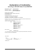
Declaration of Conformity according to ISO/IEC Guide 22 and EN45104 Manufacturer's name: Distributor's name: Distributor's address: High End Systems High End Systems 2105 Gracy Farms Lane Austin, TX 78758 USA Declares that the product: Product Name: Roadster Orbital Head System Product Number: All Product Options: All Conforms to the following EEC directives: 73/23/EEC, as amended by 93/68/EEC 89/336/EEC, as amended by 92/31/EEC and 93/68/EEC Equipment referred to in this declaration of conformity was fir
Product Modification Warning High End Systems products are designed and manufactured to meet the requirements of United States and International safety regulations. Modifications to the product could affect safety and render the product non-compliant to relevant safety standards. Mise En Garde Contre La Modification Du Produit: Les produits High End Systems sont conçus et fabriqués conformément aux exigences des règlements internationaux de sécurité.
Important Safety Information Instructions pertaining to continued protection against fire, electric shock, and injury to persons are found in Appendix A. Please read all instructions prior to assembling, mounting, and operating this equipment. Important: Informations De Sécurité: Les instructions se rapportant à la protection permanente contre les incendies, l’électrocution, excessif et aux blessures corporelles se trouvent dans l’Annexe A.
are returned for repair. The manufacturer will make the final determination as to whether or not the unit is covered by warranty. Any Product unit or parts returned to High End Systems must be packaged in a suitable manner to ensure the protection of such Product unit or parts, and such package shall be clearly and prominently marked to indicate that the package contains returned Product units or parts and with an RMA number.
Table of Contents Contacting High End Systems® ............................................................................ ii Product Modification Warning ............................................................................... iv FCC Information ................................................................................................ iv Important Safety Information ............................................................................... v Symbols ......................................
Connecting the System ..................................................................................... 11 Power Hub Connections ................................................................................. 11 Power Hub to Projector .............................................................................. 12 Power Hub to Orbital Head Connection ......................................................... 12 DMX Data Connection .......................................................................
Information Menu ............................................................................................ 26 Channels Needed .......................................................................................... 26 Display Errors ............................................................................................... 26 DMX Values Menu .......................................................................................... 26 Fixture Hours .................................................
x Roadster Orbital Head User Manual
Chapter 1: Product Overview The Roadster Orbital Movement system from High End Systems® utilizes a moving mirror head mounted on the front of a Christie Digital Roadster S+12/16 3-chip, DLP®–based projector to position a projected image anywhere in three-dimensional space. A power hub component mounts separately to allow DMX control of the Orbital Head movement and projector shutter, lamp, focus and zoom.
CHAPTER 1 Product Overview Accessories The following table lists accessories available for the Roadster Orbital Movement System from your High End dealer/distributor. For more information, contact your High End Systems dealer/ distributor or see “Contacting High End Systems” on page ii.
CHAPTER 1 Product Overview Specifications Physical Specifications Mirror Head Dimensions: 349 mm x 369 mm x 686 mm (13.7in x 14.5in x 27in). Weight: 12.7 kg (28 lbs) 348.6 mm (13.7 in) 76.7 mm (3 in) 15.8 mm (.62 in) 369.4 mm (14.5 in) 292.2 mm (11.5 in) 97mm (3.8 in) 285.2 mm (11.2 in) 176mm (6.9 in) 685.8 mm (27 in) 45° 109 mm (4.3 in) 400.6 mm (15.8 in) 116 mm (4.6 in) 386 mm (15.2 in) 299.7 mm (11.8 in) 121.4mm (4.8 in) 289.9 mm (11.4 in) 109.5mm 109.5mm (4.3 in) (4.3 in) 30° 249.6 mm (9.
CHAPTER 1 Product Overview Power Hub Dimensions: 276 mm x 301mm x 120mm (10.9in x 11.8in x 4.7in). Weight: 2.3 kg (5 lbs) 13.2 mm (.5 in) 75 mm (3 in) 40 mm (1.6 in) 60 mm (2.4 in) 276.4 mm (10.9 in) 52 mm (2.1 in) 150 mm (5.9 in) 151 mm (5.9 in) 119 mm (4.7 in) 15.5 mm (.6 in) 300.7 mm (11.8 in) Roadcase Dimensions (including casters): 1150 mm x 622 mm x 660 mm (45 in x 24.5 in x 26 in) Weight (with components loaded): 71.
CHAPTER 1 Product Overview Electrical Specifications The following electrical specifications apply to the Power Hub component of the Roadster Orbital Movement System. Warning: Class I equipment – This equipment must be earthed Universal Input from 100 – 230 VAC, (50 – 60 Hz) Rated power: 100 W Fuse: Power supply output fuse: 2.5 A, 250 V slow blow only.
CHAPTER 1 Product Overview Mirror Head to Power Hub Connection Cable: 4–conductor, 1.5 mm2 with a maximum length of 2 meters.
Chapter 2: Setup and Configuration Inspecting the Fixture The following components are shipped as the Roadster Orbital Head system: Hardware • Orbital Head fixture • Power Hub • Mounting Bracket for Christie projector Cabling • 4-pin XLR Power hub cable • RS 232 cable • US power cable • European power cable Unpack all components and verify that it is undamaged. Inspect both the outside of the components for physical damage and the optical surfaces of the Orbital Head.
CHAPTER 2 Setup and Configuration Contact a local authority for the type of power cord cap needed. When installing the power cord cap, note that the cores in the mains lead are colored in accordance with the following code: • green and yellow = earth • blue = neutral • brown = line Warning: Class 1 equipment - This equipment must be earthed. Installing a Line Cord Cap - U.K.
CHAPTER 2 Setup and Configuration System Setup Mounting Warnings: Equipment suitable for dry locations only. Do not expose this equipment to rain or moisture. Caution: If mirror surface needs to be cleaned during setup procedure, use only a mild glass cleaner (containing no ammonia) and a soft, lint-free cotton cloth to avoid scratching mirror surface. The Roadster Orbital Head system ships with a mounting bracket adapted to the Christie Roadster S+12 or S+16 high output video projectors.
CHAPTER 2 Setup and Configuration 3. Remove the three existing projector M10 x 20mm hex bolts and lock washers (B). 4. Retract projector foot (C) to minimum height to accommodate the bracket. B C 5. Slide the bracket over the projector. 6. Insert the three provided spacers (D) between the bracket and the projector 7. Reinstall the three hex bolts and washers (B) through the spacers. 8.
CHAPTER 2 Setup and Configuration Connecting the System to Power 200-230 VAC ORBITAL HEAD ROADSTER S-16K to Catalyst Media Server DVI CABLE INPUT #2 RS232 INPUT to Power MODU-LINK 110VAC 9 PIN RS-232 CABLE POWER HUB RS232 DMX-OUT 4 PIN DMX CABLE 5 PIN DMX CABLE DMX-IN to next fixture on DMX link 5 PIN DMX CABLE from DMX console or previous fixture on the DMX link Power Hub Connections Power Hub connections include: • IEC320: 100-130V Power in • RS-232 to Christie Roadster projector • 4-Pin
CHAPTER 2 Setup and Configuration Power Hub to Projector The power hub RS-232 connection to the projector allows DMX control of the projector’s shutter, lamp, focus and zoom function. Power Hub to Orbital Head Connection The Power Hub provides data and power to the Orbital Head through the two meter, 4-pin XLR cable provided. This cable should not be lengthened. Note: The cable has 1.5 mm2 cores designed to carry power to the Orbital Head. Do not substitute a microphone or similar cable.
CHAPTER 2 Setup and Configuration Test each cable with a voltage/ohm meter (VOM) to verify correct polarity and to make sure that the negative and positive pins are not grounded or shorted to the shield or to each other. Caution: Do not connect anything to the ground lug on the XLR connectors. Do not connect or allow contact between the common (cable shield) and the fixture’s chassis ground. Grounding the common could cause a ground loop and/or erratic behavior.
CHAPTER 2 Setup and Configuration To connect the Roadster Orbital Head to a DMX link: 1. Connect the male XLR connector of a DMX data cable to the controller’s DMX ‘data out’ connector. 2. Connect the Data cable’s female XLR connector to the ‘data in’ connector of the first (or next) unit on the DMX link. This connection is on the Power hub for the Orbital Head system. Place a terminator in the ‘data out’ connector of last fixture on the link Daisy-chaining Power Hubs in a DMX 512 link 3.
CHAPTER 2 Setup and Configuration To apply power, connect the appropriate Power Hub line cord into your power source. For more information on attaching a linecord, see Installing Power Cord Caps on page 7. Once connected to power, the Orbital Head will initialize (home). During this process, both mirrors on the Mirror Head rotate to locate end stops and verify that the fixture is operating correctly.
CHAPTER 2 Setup and Configuration To set the DMX start channel on the Power Hub: 1. Press the Menu button to unlock the menu system or to move back up the system to the top level menus. DMX ADDRESS MENU is the first menu item at the top level. 1. Press the Enter button to select. The display will show SET DMX START CHANNEL:###. The display will show the start channel currently assigned to the fixture. 2. Use the up and down arrows on the Navigation button to select a new DMX start channel, if necessary.
Chapter 3: Operation and Maintenance This chapter discusses the onboard menu system for the Orbital Head System. For more information on operating the fixture with a controller, consult the controller documentation.
CHAPTER 3 Operation and Maintenance Navigational Basics 1. Unlock the Menu system by pressing the Menu goes to the 2-line format. 2. Use the left and right arrows options at the current level. button for a few seconds until the display on the 4-way Navigation button to scroll through Menu 3. Stop at the desired menu and press the Enter be stored unless the Enter button is pressed. button to select. The new option will not 4. If there is another level of menu choices repeat Steps 2 and 3. 5.
CHAPTER 3 Operation and Maintenance Unlocking the Menu System To unlock the menu system, press and hold the Menu button until the display changes to the 2-line format. The menu system is protected against inadvertent menu changes by requiring the Menu button to be held for a few seconds before allowing entry to the menus. DMX Address Menu is the first option on the top menu level.
CHAPTER 3 Operation and Maintenance Level 1 Level 2 Level 3 Option/Setting scrolls between values selects enters /exits Menu System and moves up levels moves between items on same level.
CHAPTER 3 Operation and Maintenance DMX Address Menu DMX Address is the top level menu selection used to set the fixture’s DMX start channel. Use this menu option, to change the existing DMX start channel to another DMX start channel. Setting a DMX Start Channel To set the DMX start channel on the Power Hub: 1. Press the Menu button to unlock the menu system or to move back up the system to the top level menus. DMX ADDRESS MENU is the first menu item at the top level. 1. Press the Enter button to select.
CHAPTER 3 Operation and Maintenance Factory Default Settings The Orbital Head System system ships with the following factory default settings: Display Invert=AUTO Display Level=ON Mirror 2 Quick Path=OFF If any of the default settings are changed, this menu reverts to the OFF option. The ON option restores all factory defaults. To check and reset factory defaults: 1. Press the Menu button to unlock the menu system or to move back up the system to the top level menus. 2.
CHAPTER 3 Operation and Maintenance Fixture Mode Menu The Mode menu sets the module and protocol configuration and crossloads software from one fixture to other Orbital Head System systems on the link. Crossloading Fixture Software A fixture running a newer software version can load the new software to all other Orbital Head Systems on the link using the CROSSLOAD FIRMWARE menu option. To CROSSLOAD FIRMWARE from one fixture to all Orbital Head System systems on the link: 1.
CHAPTER 3 Operation and Maintenance Test Options Menu The TEST OPTIONS MENU manually homes the fixture, performs fixture self tests, and stores new boot code information. Performing fixture self tests may help identify mechanical problems in the fixture. Copying the Boot Code When new software is uploaded to a Orbital Head System, it may contain a new boot code which must be copied to each fixture. This is apparent if the fixture displays a BOOTDIFF error.
CHAPTER 3 Operation and Maintenance Self Test Menu This option displays the steps and DMX values generated as the fixture tests the motor operation of various functions. Self test can be run and viewed on all the fixture parameters sequentially, or individual parameters. To access the SELF TEST MENU: 1. Press the Menu button to unlock the menu system or to move back up the system to the top level menus. 2.
CHAPTER 3 Operation and Maintenance Information Menu The Information menu displays current fixture information such as sensor status, total fixture hours, hardware and software versions, DMX errors, and DMX data for any device on the link. Fixture hours resets are also executed in the Information Menu. Channels Needed Use this option to view the number of channels required (channel range) for the fixture’s specific configuration. The Orbital Head System requires 12 channels on a DMX link.
CHAPTER 3 Operation and Maintenance Fixture Hours Use this option to view the fixture operation time in hours and minutes. Fixture Hours Reset Use this option to reset the fixture operation time to Zero. To access the FIXTURE HOURS RESET option: 1. Press the Menu button to unlock the menu system or to move back up the system to the top level menus. 2. Use the left and right arrows on the Navigation button to scroll to the INFORMATION MENU and press the Enter button to select. 3.
CHAPTER 3 Operation and Maintenance Unique Number Each Orbital Head System has a unique number similar to a serial number. TalkBack™ protocol uses this number to identify a fixture for remote communication over a DMX link. Use this option to view the fixture’s unique number. Software Version This option display’s the fixture’s CPU board Software version. The version number is composed of: V(Major).(Minor).
CHAPTER 3 Operation and Maintenance Power Hub Maintenance Replacing the Power Hub Fuse Warning: Disconnect power before servicing. This fixture must only be serviced by qualified personnel. The following information is intended to assist qualified personnel only. Replace fuses with the specified type and rating only. To replace a fuse: 1. Disconnect power to the power supply hub. 2. Remove the three screws on the back of the power supply hub and lift the cover. 3.
CHAPTER 3 Operation and Maintenance 30 Roadster Orbital Head System User Manual
Chapter 4: DMX Programming DMX Programming Terminology A Parameter (construct) is a fixture attribute that can be controlled to modify the light beam in terms of color, beam quality and pattern, intensity, or focus (position). To program fixtures, DMX values are assigned to each of the fixture’s parameters according to that fixture’s DMX protocol. A cue (sometimes referred to as a scene or look depending on the controller used) is one set of attribute options.
CHAPTER 4 DMX Programming MSpeed (Motor Speed) The MSpeed parameter controls the time required for a motor to complete movement when changing from one position to another from the longest (DMX value = 0) to the shortest (DMX value = 65535). MSpeed provides a means for all motors to reach their target position at the same time, even though each motor may have different distances to travel. MSpeed movement is extremely smooth because the fixture controls movements independent of DMX refresh rates.
CHAPTER 4 DMX Programming Control Function The Control parameter provides access to a number of Power Hub and Projector commands from the control desk. Parameter DMX Value Shutter 0-255 0 0-255 Control 0-9 Control Option Safe Description Disables all Control settings for normal operation. 10-19 Pan & Tilt MSpeed Off Sets Pan & Tilt MSpeed off. 20-28 Display Off Sets display to off. 30-38 Display Dim Dims display characters. 40-48 Display Bright Brightens the display characters.
CHAPTER 4 DMX Programming DMX Protocol Table The Roadster Orbital Head System is patched by a DMX controller as an individual fixture on a DMX link and requires a 12-channel range. Chan # Value dec.
CHAPTER 4 DMX Programming Roadster Orbital Head System User Manual 35
CHAPTER 4 DMX Programming 36 Roadster Orbital Head System User Manual
Appendix A: MSpeed Conversion Table The following table lists the MSpeed (motor) movement times and their corresponding DMX controller values. If you have a numeric-type controller, use the Value Decimal (dec.) column. If you have a fader-type controller, use the Value Percentage (%) column. If your controller allows you to program hex values, use the Value (hex) column. Time (sec.) 0.15 0.15 0.17 0.19 0.21 0.25 0.29 0.35 0.41 0.47 0.55 0.63 0.73 0.83 0.94 1.05 1.18 1.31 1.45 1.60 1.75 1.92 2.09 2.27 2.
APPENDIX A Time (sec.) 54.09 55.02 55.96v 56.91 57.87 58.84 59.81 60.79 61.78 62.78 63.79 64.80 65.82 66.85 67.89 68.94 69.99 71.05 72.13 73.20 74.29 75.38 76.49 77.60 78.71 79.84 80.98 82.12 83.27 84.43 85.59 86.77 87.95 89.14 90.34 91.55 92.76 93.98 95.21 96.45 97.70 98.95 100.22 101.49 102.77 104.05 105.35 106.65 107.96 38 Value (dec.
CHAPTER B Safety Information Appendix B: Safety Information Warning: For Continued Protection Against Fire 1. This equipment for connection to branch circuit having a maximum overload protection of 20 A. Warning: For Continued Protection Against Electric Shock 1. If this equipment was received without a line cord plug, attach the appropriate line cord plug according to the following code: • brown–line • blue–neutral • green/yellow–earth 2.
CHAPTER B Safety Information Appendice B: Importantes Informations Sur La Sécurité Mise En Garde: Pour Une Protection Permanente Contre Les Incendies 1. Cet appareil de connection au circuit comporte une protection contre les surcharges de 20 A. Mise En Garde: Pour Une Protection Permanente Contre Les Chocs Électriques 1. Si cet équipement est livré sans prise de cable, veuillez connecter la prise de cable correcte selon le code suivant: • marron - phase • bleu - neutre • vert/jaune - terre 2.
CHAPTER B Safety Information Anhang B: Wichtige Hinweise Für Ihre Sicherheit Warnung: Zum Schutz Vor Brandgefahr 1. Dieses Gerät darf nur an eine Zweigleitung mit einem Überlastungsschutz von höchstens 20 A angeschlossen werden. Warnung: Zum Schutz Gegen Gefährliche Körperströme 1. Wenn dieses Gerät ohne einen Netzkabelstecker erhalten wurde, ist der entsprechende Netzkabelstecker entsprechend dem folgenden Code anzubringen: • Braun - Unter Spannung stehend • Blau - Neutral • Grün/Gelb - Erde 2.
CHAPTER B Safety Information Apéndice B: Información Importante De Seguridad Advertencia: Para Protección Continua Contra Incendios 1. Este equipo debe conectarse a un circuito que tenga una protección máxima contra una sobrecargas de 20 A. Advertencia: Para La Protección Continua Contra Electrocuciones 1. Si se recibió este equipo sin el conector de alimentacion, monte usted el conector correcto según ia clave siguente: • moreno - vivo • azul - neutral • verde/amarillo - tierra 2.
CHAPTER B Safety Information Appendice B: Importanti Informazioni Di Sicurezza Avvertenza: Per Prevenire Incendi 1. Questa apparecchiatura e' da collegarsi ad un circuito con una protezione da sovraccarico massima di 20 ampere. Avvertenza: Per Prevenire Le Scosse Elettriche 1. Da non montare sopra una superficie infiammabile. 2. Mantenere l' apparecchio a un minimo di 1.0 metri (3.28 piedi) di distanza dai materiali combustibili. 3.
CHAPTER B Safety Information 44 Roadster Orbital Head User Manual