RF test AT command Revision History Revision Date 0.
Contents 1. 2. 3. 4. Introduction……………………………………………………………………4 Hardware connection………………………..………………………………4 RF test AT command Description……………………………………………...4 Example……………………………………………..
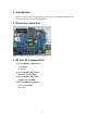
1. Introduction In this section, we will focus on how to do RF test AT command inside MC300. Users can use AT command through UART. 2. Hardware connection Note:According to the pictures of by method of jump line 3. RF test AT Command list 3.1 ICAT+RADIO_CHANNEL=n set channel n =[1~14] 3.2 ICAT+RADIO_RF_START Enter RF TX Test Mode 3.3 ICAT+RADIO_RF_STOP Stop RF TX Test Mode 3.
3.5 ICAT+RADIO_RF_GNGAIN=n Set 11 g/n TX power value N=7~20 3.
4 Example Following are some examples that demonstrate the usage of these AT commands. The following test instance is based on 802.11G AT+NDBGL=2,0 ICAT+RADIO_CHANNEL=1 ICAT+RADIO_RF_START ICAT+RADIO_RF_RATE=14 The following test instance is based on 802.11N AT+NDBGL=2,0 ICAT+RADIO_CHANNEL=1 ICAT+RADIO_RF_START ICAT+RADIO_RF_RATE=22 Note: Support only 20M The following test instance is based on 802.
FCC STATEMENT : This device complies with Part 15 of the FCC Rules. Operation is subject to the following two conditions: (1) This device may not cause harmful interference, and (2) This device must accept any interference received, including interference that may cause undesired operation. Warning: Changes or modifications not expressly approved by the party responsible for compliance could void the user's authority to operate the equipment.
FCC INFORMATION (additional) OEM INTEGRATION INSTRUCTIONS: This device is intended only for OEM integrators under the following conditions: The module must be installed in the host equipment such that 20 cm is maintained between the antenna and users, and the transmitter module may not be co-located with any other transmitter or antenna. The module shall be only used with the internal antenna(s) that has been originally tested and certified with this module.