
User's Manual


HF-LPX70 Series Wi-Fi&BLE User Manual
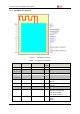
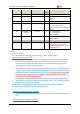
Pin
Describtion
Net Name
Signal
Type
Comments
26
GPIO14
GPIO14
I/O
GPIO14
27
UART0
UART0_RX
I
3.3V TTL UART0 Communication
Input
GPIO7
28
GPIO12
GPIO12
I/O
GPIO12
29 Wi-Fi Status nLink O
“0”
– Wi-Fi connect to router
“1”
– Wi-Fi unconncted;
Detailed functions see <Notes>
GPIO5
30
Module Boot Up
Indicator
nReady
O
“0” – Boot-up OK;
“1”
– Boot-up Fail;
GPIO4, PWM2
31 Multi-Function nReload I,PU
Detailed functions see <Notes>
GPIO3, PWM3
32
N.C
33
Module Reset
RESET
I,PU
“Low” effective reset input.
There is RC reset circuit
internally. No need of external
RC reset circuit.
<Notes>
I— Input
;O— Output
PU—InternalResistor Pull Up
; I/O: Digital I/O;Power—Power Supply
nReload Pin (Button) function:
1. When this pin is set to “low” during module boot up, the module will enter wireless
firmware and config upgrade mode. This mode is used for customer manufacture.
See Appendix to download software tools for customer batch configuration and
upgrade firmware during mass production.
2.
After module is powered up, short press this button (0.2s<“Low” <1.5s) and loose to
make the module go into Smart BLE Link config mode, waiting for APP to set router
SSID and password, config module connect to router. Recommend to use Smart Ble
Link BLE method config, may use AT+SMART CONFIG to choose other config
mode(Smart Link V8 and Smart AP Link).
See Appendix to download Smart BLE Link, Smart Link V8 and Smart AP Link APP
3. After module is powered up, long press this button ( “Low” >4s ) and loose to make
the module recover to factory setting.
High-Flying strongly suggest customer fan out this pin to connector or button
for “Manufacture” upgrade or “Smart Link” application.
nReady Pin (LED) function(Low effective):
1. OS initial finished indicator. Only after this pin output low, can the UART function be
used.
nLink Pin (LED) function(Low effective):
Shanghai High-Flying Electronics Technology Co., Ltd(www.hi-flying.com) - 10 -