HF-LPX70 Series Wi-Fi&BLE User Manual HF-LPT170 Low Power Wi-Fi +BLE Module User Manual V1.4 Overview of Characteristic Support Wi-Fi IEEE 802.11b/g/n and BLE 5.
HF-LPX70 Series Wi-Fi&BLE User Manual TABLE OF CONTENTS LIST OF FIGURES ...................................................................................................................................3 LIST OF TABLES ....................................................................................................................................4 HISTORY ..................................................................................................................................................
HF-LPX70 Series Wi-Fi&BLE User Manual LIST OF FIGURES Figure 1. Block Diagram ........................................................................................................................5 Figure 2. HF-LPT170 Appearance ........................................................................................................7 Figure 3. HF-LPT170 Pins Map .............................................................................................................8 Figure 4.
HF-LPX70 Series Wi-Fi&BLE User Manual LIST OF TABLES Table1. HF-LP170 Module Technical Specifications ..........................................................................7 Table2. HF-LPT170 Pins Definition .....................................................................................................9 Table3. Absolute Maximum Ratings:.................................................................................................11 Table4. Evaluation Kit Interface Description ...........
HF-LPX70 Series Wi-Fi&BLE User Manual HISTORY Ed.V1.006-09-2020 FirstVersion. Ed.V1.106-10-2020 Updatesomeerror description Ed.V1.207-16-2020 Update 1MB and 2MB softwaredifference. Ed.V1.308-24-2020 Add HF-LPT170, HF-LPB170, HF-LPB175 type. Ed.V1.409-16-2020 Delete 1MB version, and Add HF-LPT270,HF-LPT271 type. Shanghai High-Flying Electronics Technology Co., Ltd(www.hi-flying.
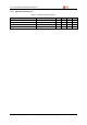
HF-LPX70 Series Wi-Fi&BLE User Manual 1. PRODUCT OVERVIEW 1.1.1 Key Application Remote equipment monitoring Asset tracking and telemetry Security Industrial sensors and controls Home automation Medical devices 1.1.2 Device Paremeters Table1. Class HF-LP170Module Technical Specifications Item Parameters Wireless standard IEEE 802.11 b/g/n Frequency range 2.412GHz-2.462GHz 802.11b: +25dBm ± 2dBm (@11Mbps) 802.11g: +23dBm ± 2dBm (@54Mbps) 802.11n: +22dBm ± 2dBm (@HT20) 802.
HF-LPX70 Series Wi-Fi&BLE User Manual StorageTemp. Humidity MSL Dimensions and Size Software Parameters Network Type Security Mechanisms Encryption Update Firmware Customization Network Protocol User Configuration -40℃- 125℃ <85% Level 3 HF-LPT270: 22.5mm x 13.5mm x 3mm HF-LPT170: 22mmx15.6mmx8mm HF-LPT271: 24mmx16mmx 3mm HF-LPB170: 23.1mm x 32.8mm x 3.5mm HF-LPB175: 41.3mm x 24.
HF-LPX70 Series Wi-Fi&BLE User Manual 1.2.1. HF-LPT170Pins Definition Figure 3. Table2. HF-LPT170 Pins Map HF-LPT170 Pins Definition Pin Describtion Net Name 1 Ground GND Signal Type Power 2 +3.3V Power VDD Power 3 Multi-Function 4 5 6 7 Comments Detailed functions see GPIO3, PWM3 Module Reset RESET I,PU “Low” effective reset input. There is RC reset circuit internally. Noneedof external RC reset circuit. UART0 UART0_RX I 3.
HF-LPX70 Series Wi-Fi&BLE User Manual Pin Describtion Net Name Signal Type Comments GPIO17 8 UART1_RX DEBUG_UART1_RX I nReady O nLink O 9 Module Boot Up Indicator 10 Wi-Fi Status 3.3V TTL UART1 Debug Input GPIO11 “0” – Boot-up OK; “1” – Boot-up Fail; GPIO4, PWM2 “0” – Wi-Fi connect to router “1” – Wi-Fi unconncted; Detailed functions see GPIO5 I— Input;O— Output PU—InternalResistor Pull Up; I/O: Digital I/O;Power—Power Supply nReload Pin (Button) function: 1.
HF-LPX70 Series Wi-Fi&BLE User Manual 1.2.2. Electrical Characteristics Table3. Parameter Absolute Maximum Ratings: Condition Work temperature range Min. -40 Typ. Max. Unit 85 °C Maximum soldering temperature IPC/JEDEC J-STD-020 260 °C ESD (Human Body ModelHBM) TAMB=25°C 2.5 KV ESD (MM) TAMB=25°C 0.25 KV Shanghai High-Flying Electronics Technology Co., Ltd(www.hi-flying.
HF-LPX70 Series Wi-Fi&BLE User Manual 1.2.3. HF-LPT170Mechanical Size HF-LPT170 modules physical size (Unit: mm) as follows: Figure 4. 1.2.4. HF-LPT170 Mechanical Dimension PCB Antenna HF modules support internal PCB antenna option.
HF-LPX70 Series Wi-Fi&BLE User Manual Figure 5. 1.2.5. Suggested Module Placement Region Evaluation Kit High-Flying provides the EVK to promote user to familiar the product and develop the detailed application. The evaluation kit shown as below, user can connect to module with the RS-232 UART, USB (Internal USB to UARTconvetor) or Wireless interface to configure the parameters, manage the module or do the some functional tests. Figure 6.
HF-LPX70 Series Wi-Fi&BLE User Manual Figure 7. HF-LPX70 EVKTypeTwo Notes: User need download USB to UART port driver from High-Flying web or contact with technical support people for more detail. The external interface description for evaluation kit as follows: Table4. Functi on Extern al Interfa ce LED Button 1.2.6. Evaluation Kit Interface Description Name Description RS23 2 Main data/command RS-232 interface,thisinterfacemaximumbaudrateis460800.
HF-LPX70 Series Wi-Fi&BLE User Manual Figure 8. 1.2.7. HF-LPT170 Order Information Hardware Typical Application Figure 9. HF-LPT170 Hardware Typical Application Notes: nReset- Module hardware reset signal. Input. Logics “0” effective. There is pull-up resister internal and no external pull-up required. When module power up or some issue happened, MCU need assert nRST signal “0” at least 10ms, then set” 1” to keep module fully reset. nLink- Module WIFI connection status indication. Output.
HF-LPX70 Series Wi-Fi&BLE User Manual (This pin is recommend to connect to LED, indicate status when the module in wireless upgrade mode) When module connects to AP (AP associated), this pin will output “0”. This signal used to judge if module already at WiFi connection status. Thers is pull-up resister internal and no external pull-up required. IfnLink function not required, can leave this pin open. nReady- Module boot up ready signal. Output. Logics “0” effective.
HF-LPX70 Series Wi-Fi&BLE User Manual APPENDIX D:CONTACT INFORMATION -----------------------------------------------------------------------------------------------------------Address:Room 1002,Building 1,No.3000,Longdong Avenue,Pudong New Area,Shanghai,China,201203 Web:www.hi-flying.com Service Online:400-189-3108/18616078755 Sales Contact: sales@hi-flying.
OEM/Integrators Installation Manual 1. List of applicable FCC rules This module has been tested and found to comply with part 15.247 requirements for Modular Approval. 2. Summarize the specific operational use conditions This module can be used in IoT devices. The input voltage to the module should be nominally 3.3VDC and the ambient temperature of the module should not exceed 85℃. HF-LPT170 has one PCB antenna with max antenna gain 2.0dBi.
9. Additional testing, Part 15 Subpart B disclaimer The final host / module combination need to be evaluated against the FCC Part 15B criteria for unintentional radiators in order to be properly authorized for operation as a Part 15 digital device.