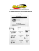
780 Professional Drive N Shreveport, LA 71105 Phone (318)524-2270 Can-Am Maverick Replacement Tie Rod Kit for Rack and Pinion Parts Diagram
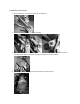
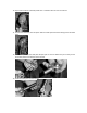
Installation Instructions 1. Remove the front tire nearest the rod you are replacing. 2. Disconnect the rod from the knuckle assembly. 3. Remove the metal band and cut the plastic boot band from the boot on the rack and pinion. The plastic boot band to the inside is going to be difficult to cut and replace. 4. Once you have cut the bands pull the boot down to expose the end.
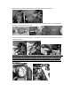
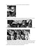
5. Using a wrench or channel locks disconnect the rod from the rack and pinion. 6. Now that you have removed the rod from the rack and pinion disconnect inner rod that holds the boot. Remove boot from the rod. 7. Connect the yoke to the rack and pinion. Use the 16 x 1.5 x 30mm socket head bolt and loctite provided in the kit. WARNING !!! IMPORTANT: For the rod to function properly and to prevent driving hazards the yoke needs to be connected in the manner shown in photo.
8. Connect the ½” Left Hand Heim Joint to the yoke using the ½”-20 x 1 ½” button head bolt and two 12mm flat washers. Place the washers on either side of the heim joint on the inside of the yoke. 9. Reattach the boot to the rack and pinion and fasten the small end using the factory clamp and the zip tie provided for the larger end. This can be difficult to fasten due to the lack of space. Loop the zip tie first then slide it over the boot then pull tight.
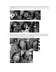
10. If you have not done so already install the ½” Left Hand Jam nut onto the rod end. 11. Connect the rod to the rack and pinion with the small tapered end connecting to the left hand heim. 12. Locate the 5/8” Heim Joint and place the 5/8” jam nut onto it. Make sure you run the jam nut all the way down to the bottom of the threads. 13. Install the heim joint into the hex bar.
14. Using a ½” drill bit or equivalent, open the hole of the knuckle assemble to ½”. 15. Take the ½ x 3 ¼”” Hex Bolt and insert one of the Hi-Alignment spacers onto the bolt. Slide the bolt into the heim joint, then place another Hi-Alignment spacer onto the bolt. 16. Insert the bolt into the knuckle assembly. Place the ½” flat washer and ½” lock nut onto the bolt and tighten. 17. FUNCTION TEST: Disconnect the shock from the arm.
Aligning the front wheels 1. Make sure that the tires are straight to sight. 2. Take a tape measure and measure from a flat spot on the front and back ends of the tire. 3. They must both be the same distance. If they do not then you will need to adjust the tie rods in or out. NOTE: A slight toe out makes the steering less sensitive and the ATV more stable. When adjusting the toe, be sure to take the time to adjust both ends of the tie rod half the required distance.