High-definition Vandal-proof Dome Camera· User Manual High-definition Vandal-proof Dome Camera User Manual UD.
High-definition Vandal-proof Dome Camera· User Manual Thank you for purchasing our product. If there are any questions, or requests, please do not hesitate to contact the dealer.
High-definition Vandal-proof Dome Camera· User Manual as outlined in UL’s Standard(s) for Safety, UL60950-1. UL Certification does not cover the performance or reliability of the security or signaling aspects of this product. UL MAKES NO REPRESENTATIONS, WARRANTIES OR CERTIFICATIONS WHATSOEVER REGARDING THE PERFORMANCE OR RELIABILITY OF ANY SECURITY OR SIGNALING RELATED FUNCTIONS OF THIS PRODUCT.
High-definition Vandal-proof Dome Camera· User Manual Regulatory Information FCC Information FCC compliance: This equipment has been tested and found to comply with the limits for a digital device, pursuant to part 15 of the FCC Rules. These limits are designed to provide reasonable protection against harmful interference when the equipment is operated in a commercial environment.
High-definition Vandal-proof Dome Camera· User Manual 2002/96/EC (WEEE directive): Products marked with this symbol cannot be disposed of as unsorted municipal waste in the European Union. For proper recycling, return this product to your local supplier upon the purchase of equivalent new equipment, or dispose of it at designated collection points. For more information see: www.recyclethis.info.
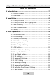
High-definition Vandal-proof Dome Camera· User Manual Table of Contents 1 Introduction ........................................................................7 1.1 Product Features ...................................................... 7 1.2 Overview ................................................................. 8 2 Installation..........................................................................9 2.1 Ceiling Mounting ...................................................... 9 2.
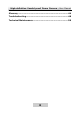
High-definition Vandal-proof Dome Camera· User Manual Glossary ................................................................................44 Troubleshooting ...................................................................48 Technical Maintenance ........................................................
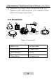
High-definition Vandal-proof Dome Camera· User Manual 1 Introduction 1.1 Product Features This series of camera adopts high-sensitive sensor and advanced circuit board design techno logy. It possesses of high resolution, low distortion, and low noise features, etc. It is extremely suitable for surveillance system and image process system.
High-definition Vandal-proof Dome Camera· User Manual Advanced 3-axis design allows this dome camera to be adjusted 0-355°horizontally and 0-75°vertically to meet different mounting requirements 1.
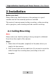
High-definition Vandal-proof Dome Camera· User Manual 2 Installation Before you start: Please make sure that the device in the package is in good condition and all the assembly parts are included. This series of camera support ceiling mounting, ceiling mounting with a gang box, wall mounting and side conduit mounting. 2.1 Ceiling Mounting Note: Please make sure that the ceiling is strong enough to withstand three times the weight of the camera. Steps: 1.
High-definition Vandal-proof Dome Camera· User Manual Side Cable Outlet Cable Outlet Screw Hole Screw Hole Drilling Template for Outdoor Day/Night Vandal-proof Dome Camera Screw Hole Figure 2-1 The Drill Template 3. Loosen the screws with the supplied L-shape screwdriver to open the lower dome. 4. Remove the black liner.
High-definition Vandal-proof Dome Camera· User Manual Note: If you want to install the camera to the cement ceiling, you need to screw 3 expansion screws into the 3 drilled holes first. 5. Route the cables and connect the power supply and output the video on a monitor. 6. Secure the dome camera to the ceiling with 3 self-tapping screws. Refer to Figure 2-3. Figure 2-3 Secure the Camera to the Ceiling 7. Adjust the Lens. 1). View the camera image via the monitor. 2).
High-definition Vandal-proof Dome Camera· User Manual 4). Rotate the tilting table to adjust the tilting position of the camera. 0 to 75°is adjustable. 5). Rotate the lens to adjust the azimuth angle of the image. 0 to 355°is adjustable. 6). Tighten the lock screw. 7). Move the focus lever and zoom lever to adjust the focus and the zoom. Pan Tilt Rotation Figure 2-4 Lens Adjustment 8. Attach the black liner back to the camera. 9. Attach the lower dome back to the camera and secure it with the screws.
High-definition Vandal-proof Dome Camera· User Manual Figure 2-5 Install the Black Liner and the Lower Dome 10. Remove the protection film softly to complete the installation. Note: Remove the protection film after the installation is completed in case of the image problem caused by the scrape of the lower dome. 2.2 Ceiling Mounting with a gang box Steps: 1. Secure the adapter ring to the gang box.
High-definition Vandal-proof Dome Camera· User Manual Figure 2-6 Secure the Adapter Ring 2. Loosen the screws to open the lower dome. 3. Remove the black liner. Figure 2-7 Remove the Black Liner 4. Route the cables and connect the power supply and output the video on a monitor 5. Secure the camera to the adapter ring w ith the screws.
High-definition Vandal-proof Dome Camera· User Manual Figure 2-8 Install the Camera 6. Adjust the lens. 1). View the camera image via the monitor. 2). Loosen the lock screw besides the lens 3). Rotate the panning table to adjust the panning position of the camera. 0 to 355°is adjustable. 4). Rotate the tilting table to adjust the tilting position of the camera. 0 to 75°is adjustable. 5). Rotate the lens to adjust the azimuth angle of the image. 0 to 355°is adjustable. 6). Tighten the lock screw. 7).
High-definition Vandal-proof Dome Camera· User Manual Figure 2-9 Attach the Black Liner 8. Attach the lower dome back to the camera and secure it with the screws. Figure 2-10 Install the Lower Dome 9. Remove the protection film softly to complete the installation.
High-definition Vandal-proof Dome Camera· User Manual Remove the protection film after the installation is completed in case of the image problem caused by the scrape of the lower dome. 2.3 Wall Mounting Note: Please make sure that the wall is strong enough to withstand three times the weight of the camera. Steps: 1. Drill four expansion screw holes on the wall. 2. Secure the mount to the wall w ith the expansion screws. 3. Insert the adapter ring to the mount.
High-definition Vandal-proof Dome Camera· User Manual Figure 2-12 Install the Camera 7. Route the cables and connect the power supply and output the video on a monitor. 8. Adjust the Lens. 1). View the camera image via the monitor. 2). Loosen the lock screw besides the lens 3). Rotate the panning table to adjust the panning position of the camera. 0 to 355°is adjustable. 4). Rotate the tilting table to adjust the tilting position of the camera. 0 to 75°is adjustable. 5).
High-definition Vandal-proof Dome Camera· User Manual 7). Move the focus lever and zoom lever to adjust the focus and the zoom. 9. Attach the black liner back to the camera. Figure 2-13 Install the Black Liner 10. Attach the lower dome back to the camera and secure it with the screws.
High-definition Vandal-proof Dome Camera· User Manual 11. Remove the protection film softly to complete the installation. Note: Remove the protection film after the installation is completed in case of the image problem caused by the scrape of the lower dome. 2.4 Side Conduit Cabling There are two cabling methods selectable for this series of camera. One is to route the cable through the ceiling, and the other is to route the cable though the side conduit. Steps: 1.
High-definition Vandal-proof Dome Camera· User Manual 3. Connect the corresponding power/video cables. 4. Screw the conduit to the water-proof plug to complete the installation. Figure 2-16 Connect the Conduit to the Camera 2.
High-definition Vandal-proof Dome Camera· User Manual Notes: Please make sure that the power adapter can match with the camera. The standard power supply of the camera is 12V DC or 24V AC (Please refer to technical specifications for more details). Figure 2-18 The Power/Video Cable Notes: Please make sure that the power adapter can match with the camera. The standard power supply of the camera is 12V DC (Please refer to technical specifications for more details).
High-definition Vandal-proof Dome Camera· User Manual 3 Menu Operations 3.
High-definition Vandal-proof Dome Camera· User Manual nch/Russian/ Portuguese/ Spanish/ German CAMERA RESET EXIT/SAVE ALL 3.2 Lens Settings Move the cursor to LENS, and then set the menu button left/right to select MANUAL or AUTO. Selecting MANUAL mode, the iris is set at the maximum value, and it is not configurable. Selecting AUTO mode, press the menu button to enter the AUTO IRIS submenu.
High-definition Vandal-proof Dome Camera· User Manual MODE: AUTO, OPEN, and CLOSE are selectable for iris mode. Selecting auto means the iris is adjusted automatically; selecting open means the iris is fully open; and selecting close mean the iris is totally closed. SPEED: Adjust the iris speed. The higher the value is, the faster the speed of the auto iris is. The value ranges from 0 to 255. Note: It is recommended that you adjust the iris speed only when the iris vibrates. 3.
High-definition Vandal-proof Dome Camera· User Manual In HIGH LUMINANCE condition, the SHUTTER speed and AUTO IRIS level is modified automatically according to the BRIGHTNESS value. MODE SHUT+AUTO IRIS and AUTO IRIS are available when the LENS type is AUTO IRIS. When the LENS type is Manual, the iris is fixed and only SHUT option is provided. BRIGHTNESS The value ranges from 0 to 255. In LOW LUMINA NCE condition, the AGC can be adjusted automatically according to the BRIGHTNESS value.
High-definition Vandal-proof Dome Camera· User Manual In the MANUAL SETUP submenu, it only supports SHUT+AGC. You can adjust the SHUTTER speed and AGC value to maintain the brightness level of the camera. SHUTTER Manually set the shutter speed. 1/50, 1/120, 1/250, 1/500, 1/1k, 1/2k, 1/4k, and 1/10k are selectable for PAL standard. 1/60, 1/100, 1/250, 1/500, 1/1k, 1/4k, and 1/10k are selectable for NTSC standard. AGC 6.00, 12.00, 18.00, 24.00, 30.00, 36.00, 42.00, and 44.
High-definition Vandal-proof Dome Camera· User Manual 3.4 White Balance Setting Move the cursor to the White Balance, and select ATW, PUSH, PUSH LOCK, USER1, USER2, ANTI CR and MANUAL by setting the menu button to left/right. ATW(Auto Tracking White Balance) In ATW mode, white balance is continuously being adjusted in real-time according to the color temperature of the scene illumination. SPEED The speed can be set from 0 to 255. DELAY CNT It’s the response time when the color temperature changes.
High-definition Vandal-proof Dome Camera· User Manual USER 1/USER2 USER 1 is the indoor mode and it is suitable for the indoor environment. B-Gain and R-Gain are adjustable. USER 2 is suitable for the fluorescent light environment. B-Gain and R-Gain are adjustable. USER 1 WB B-GAIN R-GAIN ---|-----030 ---|-----033 RETURN Figure 3-5 USER 1 WB MANUAL Selecting MANUAL and pressing the button to enter the MANUAL WB submenu. Customize the LEVEL value on your demand.
High-definition Vandal-proof Dome Camera· User Manual In the PUSH mode, the viewed image retains color balance automatically. The color in the image balances according to the color temperature. PUSH LOCK In the PUSH LOCK mode, you can select a scene, and manually adjust the white balance, and then lock the color temperature. It is suitable for the environment which the color temperature slightly changes.
High-definition Vandal-proof Dome Camera· User Manual 3.6 Picture Adjust Setting Move the cursor to PICT ADJUST. Press the confirm button to enter the PICT ADJUST submenu. MIRROR, BRIGHTNESS, CONTRAST, SHARPNESS, HUE, and GAIN are adjustable. MIRROR If you turn the MIRROR function on, the image w ill be flipped horizontally. It looks like the image in the mirror. BRIGHTNESS The brightness is adjustable from 0 to 255.
High-definition Vandal-proof Dome Camera· User Manual PICT ADJUST MIRROR BRIGHTNESS CONTRAST SHARPNESS HUE GAIN OFF |-------- 000 ----|---- 128 ----|---- 128 ----|---- 128 ----|---- 128 RETURN Figure 3-7 PICT ADJUST 3.7 ATR Setting ATR is the digital dynamic range function which can adjust the brightness and contrast level of the image, and balance the brightness level of the whole image. Move the cursor to ATR. Set the button left/right to select ON or OFF.
High-definition Vandal-proof Dome Camera· User Manual ATR LUMINANCE CONTRAST LOW LOW RETURN Figure 3-8 ATR 3.8 Motion Detection Setting There are two kinds of MOTION DET panes: BLOCK DISP and MONITOR AREA. Two panes can take effect simultaneously. BLOCK DISP Steps: 1. Move the cursor to MOTION DET, and select ON and press the menu button to enter the submenu. 2. Position the cursor on DETECT SENSE, and set the menu button left/right to adjust the sensitivity level. 0 to 127 are selectable. 3.
High-definition Vandal-proof Dome Camera· User Manual 7. Return to the MAIN MENU and click SAVE ALL. 8. You can find the BLOCK DISP take effect after you exit the main menu. MONITOR AREA Steps: 1. Move the cursor to MOTION DET, select ON and press the menu button to enter the submenu. 2. Position the cursor on DETECT SENSE, and set the menu button left/right to adjust the sensitivity level. 3. Position the cursor on MONITOR AREA. Select OFF to disable area motion detection.
High-definition Vandal-proof Dome Camera· User Manual MOTION DET DETECT SENSE BLOCK DISP MONITOR AREA AREA SEL TOP BUTTOM LEFT RIGHT ----|---- 111 OFF ON 1/4 ----|---- 128 ----|---- 128 ----|---- 128 ----|---- 128 RETURN Figure 3-9 MOTION DET 3.9 Privacy Mask Setting This feature allows you to cover certain areas which you don’t want them to be viewed or recorded. Up to 8 privacy areas are configurable. Steps: 1. Move the cursor to PRIVACY, and press menu button to enter the PRIVACY submenu. 2.
High-definition Vandal-proof Dome Camera· User Manual COLOR There are 8 colors available. TRANSP 1.00, 0.75, 0.50, and 0.00 are selectable. PRIVACY AREA SEL TOP BUTTOM LEFT RIGHT COLOR TRANSP MOSAIC 1/8 ----|---- 128 ----|---- 128 ----|---- 128 ----|---- 128 1 0.00 OFF RETURN Figure 3-10 PRIVACY Note: When the motion detection is on, up to 4 privacy areas are configurable. 3.
High-definition Vandal-proof Dome Camera· User Manual In AUTO mode, the day mode and the night mode can sw itch automatically. Steps: 1. After moving the cursor to DAY/NIGHT, set the menu button left/right to select AUTO. 2. Press menu button to enter the submenu. BURST Burst is an analog video, composite video signal generated by a video-signal generator used to keep the chrominance subcarrier synchronized in a color television signal. Select ON or OFF to enable or disable the color burst function.
High-definition Vandal-proof Dome Camera· User Manual DAY/NIGHT BURST DELAY CNT DAY→NIGHT NIGHT→DAY OFF |--------000 ---|-----003 ---|-----005 RETURN Figure 3-11 DAY/NIGHT B/W Mode Setting BURST: In the B/W submenu, select ON or OFF to enable or disable the color burst function. IR OPTIMIZER: The camera will calculate the image brightness by the DSP, and suppress the IR brightness if the image is overexposed caused by the IR LED.
High-definition Vandal-proof Dome Camera· User Manual There is no external triggered output for this series of dome camera: For the dome cameras which don’t support IR, the EXT 1/EXT 2 is not supported. For the dome cameras which support IR, if you select EXT 1/EXT 2, the day mode switches to the night mode automatically at the same time the IR LED turns on. 3.11 NR Setting Noise Reduction is used to reduce the noise in the video signal.
High-definition Vandal-proof Dome Camera· User Manual 3.12 Camera ID Setting On Camera ID submenu, you can customize the camera ID. It also allows you to adjust the camera ID position on the monitor screen. This series of camera supports up to 52 characters. Select OFF to disable the Camera ID. Select ON to enable the Camera ID. Customizing the camera ID Steps: 1. Set it to ON, and press the menu button to enter the submenu. 2.
High-definition Vandal-proof Dome Camera· User Manual Steps: 1. Move the cursor to POS, and press the menu button to enter the position setting interface. 2. Set the menu button up/down/left/right to position the camera ID. 3. Press the button to save the position and exit. CAMERA ID ABCDEFGHIJKLMNOPQRSTUV WXYZ0123456789-!”#$%&’ ()_` , ¥:;<= >?@\^*.x+/ ← → ↑ ↓ CLR POS RETURN Figure 3-14 CAMERA ID 3.13 SYNC Setting Both internal and line lock synchronization are available.
High-definition Vandal-proof Dome Camera· User Manual Note: Internal synchronization is the default SYNC method. Set the menu button to right for about 2 seconds, you can switch the SYNC mode to line-lock from the SYNC settings. Perform the same operation to switch it to internal synchronization from the line-lock. 3.14 Language Setting This series of camera supports multi-language. English (default), Chinese, Japanese, French, Russian, Portuguese, Spanish, and German are selectable. Steps: 1.
High-definition Vandal-proof Dome Camera· User Manual The defective pixel correct function may not be displayed on the menu; you can enable the function by following the steps below. Steps: 1. Exit the OSD menu to the live view screen. 1. Switch and hold the menu button to the left for 2 seconds until you see the message of “COVER-UP LENS/CLOSE IRIS”. 2. Cover the lens or close the iris to prevent the light from entering the lens. 3. Press the menu button to confirm.
High-definition Vandal-proof Dome Camera· User Manual Glossary Note: The glossary gives brief explanations to the basic operation principle or the basic function of the camera. However, it doesn’t mean the listed functions are all supported by this series of camera. Please take the actual function in the corresponding specification as the standard. Definition: Definition is the degree to distinguish the edge between two parts clearly.
High-definition Vandal-proof Dome Camera· User Manual signal remains essentially. When under low illumination, AGC will regulate the gain and amplification of the video signal. S/N ratio: It is the ratio of Signal voltage and no ise voltage. The ratio is larger, the effect of noise is less, and the image is clearer. White Balance: White balance is the white rendition function of the camera to adjust the color temperature according to the environment automatically.
High-definition Vandal-proof Dome Camera· User Manual This function allows you to block or mask certain area of a scene, thus prevent the personal privacy from recording or live view ing. OSD (On-Screen Display): OSD is the texts superimposed on a screen. It can show the menu on the screen. Synchronous System: Synchronization of the camera usually contains power synchronization and internal synchronization.
High-definition Vandal-proof Dome Camera· User Manual CCD besides processing the noise in the separated Y video signal and C video signal. HLC (High Light Compensation): The HLC is capable of detecting and reversing the bright spots in the picture (such as headlights) to black so as to achieve optimum picture quality. Digital Zoom: Digital zoom helps to crop the entire image, and then d igitally enlarge the size of a portion of image that is needed to zoom in on.
High-definition Vandal-proof Dome Camera· User Manual Troubleshooting Problem 1: Why does the camera restart intermittently? And the problem is much more serious when infrared lights of IR camera are turned on at night. Possible Reasons: The main and common reason is power supply shortage. This problem may happen to the IR camera especially at night, because the infrared lights are turned on at night and increase the power consumption.
High-definition Vandal-proof Dome Camera· User Manual Or you can use a C/CS adapter ring between the camera and the lens with C lens mount. Problem 3: The camera is installed w ith an auto-iris lens. You adjust the focus to get a clear image in the daytime, but the image is defocused at night. Possible Reasons: In the daytime, the illumination is high, so the iris is adjusted to a small size automatically. The DOF (depth of field) is long.
High-definition Vandal-proof Dome Camera· User Manual Auto-iris lens connector is loose contact. Or the iris driven mode of the camera does not match with the mode of auto-iris lens. To Solve the Problem: Check the auto-iris lens connector to ensure good contact. Set the iris driven mode of the camera the same as the m ode of lens. The modes can be VD (video drive) or DD (direct drive). DD mode is commonly used. Technical Maintenance Lens Maintenance The lens surface is plated an anti-reflection coating.
High-definition Vandal-proof Dome Camera· User Manual The bubble is of transparent plastic. The dust, oil and finger print, etc. will cause scratch or image blur. Please refer to the fo llowing method to clean the bubble. Handling dust Use oil free soft brush or blowing dust ball to clean the dust. Handling o il Steps: 1. Wipe off the water-drop or oil by soft cloth and dry the bubble. 2.
High-definition Vandal-proof Dome Camera· User Manual 52