Digital Video Recorder User Manual UD.
User Manual of Digital Video Recorder User Manual COPYRIGHT ©2015 Hangzhou Hikvision Digital Technology Co., Ltd. ALL RIGHTS RESERVED. Any and all information, including, among others, wordings, pictures, graphs are the properties of Hangzhou Hikvision Digital Technology Co., Ltd. or its subsidiaries (hereinafter referred to be “Hikvision”).
User Manual of Digital Video Recorder Regulatory Information FCC Information FCC compliance: This equipment has been tested and found to comply with the limits for a Class A digital device, pursuant to part 15 of the FCC Rules. These limits are designed to provide reasonable protection against harmful interference when the equipment is operated in a commercial environment.
User Manual of Digital Video Recorder Safety Instruction These instructions are intended to ensure that user can use the product correctly to avoid danger or property loss. The precaution measure is divided into “Warnings” and “Cautions” Warnings: Serious injury or death may occur if any of the warnings are neglected. Cautions: Injury or equipment damage may occur if any of the cautions are neglected.
User Manual of Digital Video Recorder Preventive and Cautionary Tips Before connecting and operating your device, please be advised of the following tips: • • • • • Ensure unit is installed in a well-ventilated, dust-free environment. Unit is designed for indoor use only. Keep all liquids away from the device. Ensure environmental conditions meet factory specifications. Ensure unit is properly secured to a rack or shelf.
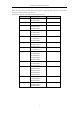
User Manual of Digital Video Recorder Thank you for purchasing our product. If there is any question or request, please do not hesitate to contact dealer. The figures in this manual are for reference only. This manual is applicable to the models listed in the following table.
User Manual of Digital Video Recorder Product Key Features General Connectable to HD-TVI and analog cameras; Connectable to the Coaxitron camera/dome with long transmission distance; Connectable to IP cameras; The IP camera connection is not supported by DS-7100; Each channel supports dual-stream. Main stream supports up to 1080P resolution and sub-stream supports up to WD1 resolution; The DS-7100-E1 and DS-7200-E1/E2 support up to 720P resolution.
User Manual of Digital Video Recorder Recording and Playback Holiday recording schedule configuration; Cycle and non-cycle recording modes; Normal and event video encoding parameters; Multiple recording types: manual, continuous, alarm, motion, motion | alarm, motion & alarm and VCA; DS-7100 does not support VCA triggered recording type.
User Manual of Digital Video Recorder Importing and exporting of configuration file of devices; Getting cameras type information automatically.
User Manual of Digital Video Recorder Table of Contents Product Key Features ................................................................................................................................. 6 Chapter 1 Introduction .................................................................................................................................. 13 1.1 Front Panels ...............................................................................................................................
User Manual of Digital Video Recorder 4.3 PTZ Control Panel ......................................................................................................................... 75 Chapter 5 Recording Settings ....................................................................................................................... 76 5.1 Configuring Recording Parameters ............................................................................................... 77 5.2 Configuring Record Schedule .
User Manual of Digital Video Recorder 9.2.1 Configuring Extranet Access ............................................................................................. 147 9.2.2 Configuring PPPoE Settings .............................................................................................. 152 9.2.3 Configuring NTP Server .................................................................................................... 152 9.2.4 Configuring SNMP .............................................
User Manual of Digital Video Recorder 13.5 Managing User Accounts............................................................................................................. 196 13.5.1 Adding a User .................................................................................................................... 196 13.5.2 Deleting a User .................................................................................................................. 198 13.5.3 Editing a User ..........................
User Manual of Digital Video Recorder Chapter 1 Introduction 13
User Manual of Digital Video Recorder 1.1 Front Panels Figure 1. 1 Front Panel of DS-7100 Table 1. 1 Description of Front Panel No. Icon Description 1 Indicator turns red when DVR is powered up. 2 Indicator lights in red when data is being read from or written to HDD. 3 Indicator blinks blue when network connection is functioning properly. Figure 1. 2 Front Panel of DS-7204/7208HGHI-SH Figure 1. 3 Front Panel of DS-7216HGHI-SH Please refer to Figure 1.2 and Figure 1.
User Manual of Digital Video Recorder No. Name Function Description panel is turned on. Status indicator blinks red when data is being read from or written to STATUS HDD. Tx/Rx indictor blinks yellow when network connection is Tx/Rx functioning properly. Receiver for IR remote 2 IR Receiver 3 USB Interfaces Universal Serial Bus (USB) ports for additional devices such as USB mouse and USB Hard Disk Drive (HDD). Figure 1. 4 Front Panel of DS-7200HQHI-SH Table 1. 3 Description of Front Panel No.
User Manual of Digital Video Recorder No. Name Function Description Delete characters before cursor; Check the checkbox and select the ON/OFF switch; Start/stop record clipping in playback. Enter numeral “6”; 6/MNO/PLAY Enter letters “MNO”; In Playback mode, it is used for direct access to playback interface. Enter numeral “7”; 7/PQRS/REC Enter letters “PQRS”; Manual record, for direct access to manual record interface; manually enable/disable record.
User Manual of Digital Video Recorder Figure 1. 5 Front Panel of DS-7300HGHI-SH and DS-7300HQHI-SH Table 1. 4 Description of Front Panel No. Name POWER READY STATUS 1 ALARM Ready indicator is normally green, indicating that the DVR is functioning properly.
User Manual of Digital Video Recorder No. Name Function Description Exit and back to the previous menu. Enter numeral “5”; Enter letters “JKL”; 5/JKL/EDIT Delete characters before cursor; Check the checkbox and select the ON/OFF switch; Start/stop record clipping in playback. Enter numeral “6”; 6/MNO/PLAY Enter letters “MNO”; In Playback mode, it is used for direct access to playback interface.
User Manual of Digital Video Recorder No. Name Function Description 7 USB Interface 8 IR Receiver Universal Serial Bus (USB) ports for additional devices such as USB mouse and USB Hard Disk Drive (HDD). Receiver for IR remote control. Figure 1. 6 Front Panel of DS-8100-SH Table 1. 5 Description of Front Panel No. Name ALARM READY STATUS 1 Status Indicators HDD Tx/Rx GUARD Function Description Alarm indicator turns red when a sensor alarm is detected.
User Manual of Digital Video Recorder No. Name Function Description The ENTER button is used to confirm selection in any of the menu modes. It can also be used to tick checkbox fields. ENTER In Playback mode, it can be used to play or pause the video. In single-frame Playback mode, pressing the button will advance the video by a single frame. In Auto-switch mode, it can be used to stop /start auto switch. Move the active selection in a menu. It will move the selection up and down.
User Manual of Digital Video Recorder No. Name Function Description Press the button will help you return to the Main menu (after successful login). Press and hold the button for 5 seconds will turn off audible key MENU/WIPER beep. In PTZ Control mode, the MENU/WIPER button will start wiper (if applicable). In Playback mode, it is used to show/hide the control interface. Switch between single screen and multi-screen mode.
User Manual of Digital Video Recorder The indicator turns off when the device is unarmed. The arm/disarm status can be changed by pressing and holding on the ESC button for more than 3 seconds in live view mode. 2 IR Receiver 3 Front Panel Lock 4 DVD-R/W Receiver for IR remote You can lock or unlock the panel by the key. Slot for DVD-R/W. Switch to the corresponding channel in Live view or PTZ Control mode. Input numbers and characters in Edit mode.
User Manual of Digital Video Recorder In PTZ Control mode, it is used to adjust the focus in conjunction with the A/FOCUS+ button. Enter the PTZ Control mode. PTZ/IRIS- In the PTZ Control mode, it is used to adjust the iris of the PTZ camera. The DIRECTION buttons are used to navigate between different fields and items in menus. In the Playback mode, the Up and Down button is used to speed up and DIRECTION slow down recorded video.
User Manual of Digital Video Recorder 1.2 IR Remote Control Operations The DVR may also be controlled with the included IR remote control, shown in Figure 1. 8. Batteries (2×AAA) must be installed before operation. Figure 1. 8 Remote Control The keys on the remote control closely resemble the ones found on the front panel. Refer to Table 1. 7, they include: Table 1. 7 Description of the IR Remote Control Buttons No. Name Description Power on/off the device.
User Manual of Digital Video Recorder No. Name Description It is also used to turn audio on/off in the Playback mode. Navigate between different fields and items in menus. In the Playback mode, the Up and Down button is used to speed up and DIRECTION Button slow down recorded video. The Left and Right button will select the next and previous record files. In Live View mode, these buttons can be used to cycle through channels. In PTZ control mode, it can control the movement of the PTZ camera.
User Manual of Digital Video Recorder 2. Batteries are fresh and not out of charge. 3. IR receiver is not obstructed. If the remote still cannot function properly, please change the remote and try again, or contact the device provider.
User Manual of Digital Video Recorder 1.3 USB Mouse Operation A regular 3-button (Left/Right/Scroll-wheel) USB mouse can also be used with this DVR. To use a USB mouse: Steps: 1. Plug USB mouse into one of the USB interfaces on the front panel of the DVR. 2. The mouse should automatically be detected. If in a rare case that the mouse is not detected, the possible reason may be that the two devices are not compatible, please refer to the recommended the device list from your provider.
User Manual of Digital Video Recorder 1.4 Input Method Description Figure 1. 9 Soft Keyboard Description of the buttons on the soft keyboard: Table 1.
User Manual of Digital Video Recorder 1.5 Rear Panel The rear panel vaires according to different models. Please refer to the actual product. The following figures are for reference only. Figure 1. 10 DS-7100 Table 1. 10 Description of Front Panel No. Item Description 1 VIDEO IN BNC interface for TVI and analog video input. 2 HDMI HDMI video output connector. 3 VGA DB15 connector for VGA output. Display local video output and menu. 4 AUDIO OUT RCA connector. 5 AUDIO IN RCA connector.
User Manual of Digital Video Recorder 6 USB Port Universal Serial Bus (USB) port for additional devices. 7 Network Interface Connector for network 8 RS-485 Interface Connector for RS-485 devices. 9 Power Supply 12V DC power supply. 10 Power Switch Switch for turning on/off the device. 11 GND Ground 12 Alarm In/Out (for Connectors for alarm inputs and alarm outputs. DS-7200HQHI-SH only) Figure 1. 13 DS-7316HQHI-SH and DS-7316HGHI-SH Figure 1. 14 DS-7332HGHI-SH Figure 1.
User Manual of Digital Video Recorder Figure 1. 16 DS-8132HGHI-SH Figure 1. 17 DS-8100/9000HQHI-SH Table 1. 12 Description of Front Panel No. Item Description 1 VIDEO IN BNC interface for TVI and analog video input. VIDEO OUT BNC connector for video output. 2 CVBS output is not provided by DS-7324/7332HGHI-SH and DS-8124/8132HGHI-SH series. 3 AUDIO IN RCA connector 4 USB Port Universal Serial Bus (USB) port for additional devices. HDMI HDMI video output connector.
User Manual of Digital Video Recorder No. Item Description 14 eSATA Connects external SATA HDD, CD/DVD-RW. 15 RS-232 Interface Connector for RS-232 devices.
User Manual of Digital Video Recorder Chapter 2 Getting Started 33
User Manual of Digital Video Recorder 2.1 Starting Up and Shutting Down the DVR Purpose: Proper startup and shutdown procedures are crucial to expanding the life of the DVR. Before you start: Check that the voltage of the extra power supply is the same with the DVR’s requirement, and the ground connection is working properly. Starting up the DVR Steps: 1. Check the power supply is plugged into an electrical outlet.
User Manual of Digital Video Recorder Do not press the POWER button again when the system is shutting down. The device remains standby mode after shutting down, and the POWER indicator turns red; you can turn on the device by pressing the POWER button on the remote control. Rebooting the DVR While in the Shutdown menu (Figure 2. 1), you can also reboot the DVR. Steps: 1. Enter the Shutdown menu by clicking Menu > Shutdown. 2. Click the Logout button to log out or the Reboot button to reboot the DVR.
User Manual of Digital Video Recorder 2.2 Setting the Admin Password Purpose: For the first-time access, you need to activate the device by setting an admin password. No operation is allowed before activation. You can also activate the device via Web Browser, SADP or Client Software. Steps: 1. Input the same password in the text field of Create New Password and Confirm New Password. Figure 2.
User Manual of Digital Video Recorder 2.3 Using the Wizard for Basic Configuration By default, the Setup Wizard starts once the device has loaded. Figure 2. 5 Start Wizard Interface Operating the Setup Wizard: 1. The Start Wizard can walk you through some important settings of the device. If you don’t want to use the Start Wizard at that moment, click Exit. You can also choose to use the Start Wizard next time by leaving the “Start wizard when device starts?” checkbox checked. 2.
User Manual of Digital Video Recorder Figure 2. 7 General Network Configuration 1 self-adaptive 10M/100M network interface for DS-7100, DS-7204/7208HGHI-SH and DS-7200HGHI-E1/E2; 2 self-adaptive 10M/100M/1000M network interfaces for DS-8100HQHI&HGHI-SH series, with three working modes configurable: multi-address, load balance, network fault tolerance; and 1 self-adaptive 10M/100M/1000M network interface for other models. 4.
User Manual of Digital Video Recorder Figure 2. 9 HDD Management 7. To initialize the HDD, click the Init button. Initialization will remove all the data saved in the HDD. 8. Click Next to enter the IP Camera Management window (only supported by HDVR series). 9. Click Search to search the online IP Camera and the Security status shows whether it is active or inactive. Before adding the camera, make sure the IP camera to be added is in active status.
User Manual of Digital Video Recorder Figure 2. 11 Record Settings 12. Click OK to complete the wizard settings.
User Manual of Digital Video Recorder 2.4 Login and Logout 2.4.1 User Login Purpose: If the device has logged out, you must login the device before operating the menu and other functions. Steps: 1. Select the User Name in the dropdown list. Figure 2. 12 Login Interface 2. Input Password. 3. Click OK to log in. In the Login dialog box, if you have entered the wrong password for 7 times, the current user account will be locked for 60 seconds. Figure 2. 13 User Account Protection 2.4.
User Manual of Digital Video Recorder Figure 2. 14 Logout 2. Click Logout. After you have logged out the system, menu operation on the screen is invalid. It is required to input a user name and password to unlock the system.
User Manual of Digital Video Recorder 2.5 Adding and Connecting the IP Cameras This section is not available for the DS-7100 series DVR. 2.5.1 Setting the Admin Password for the IP Camera Purpose: Before adding the camera, make sure the IP camera to be added is in active status. Steps: 1. Select the Add IP Camera option from the right-click menu in live view mode or click Menu> Camera> Camera to enter the IP camera management interface.
User Manual of Digital Video Recorder 3. Set the password of the camera to activate it. Use Admin Password: when you check the checkbox, the camera (s) will be configured with the same admin password of the operating NVR. Figure 2. 17 Set New Password Create New Password: If the admin password is not used, you must create the new password for the camera and confirm it.
User Manual of Digital Video Recorder Figure 2. 18 Adding IP Camera Interface 2. The online cameras with same network segment will be detected and displayed in the camera list. 3. Select the IP camera from the list and click the button to add the camera (with the same admin password of the DVR’s). Or you can click the One-touch Adding button to add all cameras (with the same admin password) from the list.
User Manual of Digital Video Recorder Camera (Custom) interface. Figure 2. 20 Custom Adding IP Camera Interface 2) You can edit the IP address, protocol, management port, and other information of the IP camera to be added. If the IP camera to add has not been actiavated, you can activate it from the IP camera list on the camera management interface. 3) Click Add to add the camera.
User Manual of Digital Video Recorder Table 2. 1 Connectable IP Cameras for Different Models Number of Connectable IP Cameras Series Default Models DS-7200HGHI-E1 DS-7200HGHI-E2 DS-7200HGHI-SH (without disabling Max.
User Manual of Digital Video Recorder click the icon to get the exception information of camera. Play the live video of the connected Advanced settings of the camera. camera. Show the security status of the camera Upgrade the connected IP camera. Security to be active/inactive or the password strength (strong/medium/weak/risk) 2.5.3 Editing the Connected IP Cameras and Configuring Customized Protocols This section is provided for the DS-7300 and DS-8100 models only which support the ONVIF protocol.
User Manual of Digital Video Recorder Figure 2. 23 Network Configuration of the Camera 2. You can edit the network information and the password of the camera. Figure 2. 24 Password Configuration of the Camera 3. Click OK to save the settings and exit the interface. Configuring the customized protocols Purpose: To connect the network cameras which are not configured with the standard protocols, you can configure the customized protocols for them. Steps: 1.
User Manual of Digital Video Recorder Figure 2. 25 Protocol Management Interface There are 16 customized protocols provided in the system, you can edit the protocol name; and choose whether to enable the sub-stream. 2. Choose the protocol type of transmission and choose the transfer protocols. Before customizing the protocol for the network camera, you have to contact the manufacturer of the network camera to consult the URL (uniform resource locator) for getting main stream and sub-stream.
User Manual of Digital Video Recorder Figure 2. 26 Protocol Setting 3. Choose the protocols you just added to validate the connection of the network camera.
User Manual of Digital Video Recorder Chapter 3 Live View 52
User Manual of Digital Video Recorder 3.1 Introduction of Live View Live view shows you the video image getting from each camera in real time. The DVR will automatically enter Live View mode when powered on. It is also at the very top of the menu hierarchy, thus hitting the ESC many times (depending on which menu you’re on) will bring you to the Live View mode.
User Manual of Digital Video Recorder 3.2 Operations in Live View Mode In live view mode, there are many functions provided. The functions are listed below. • Single Screen: show only one screen on the monitor. • Multi-screen: show multiple screens on the monitor simultaneously. • Auto-switch: the screen is auto switched to the next one. And you must set the dwell time for each screen on the configuration menu before enabling the auto-switch. Menu>Configuration>Live View>Dwell Time.
User Manual of Digital Video Recorder The √ means the interface is in use, × means the interface is out of use or the connection is invalid. And the HDMI, VGA and CVBS can be used at the same time. For Other Models For the other models, the priority level for the main and aux output is HDMI/VGA>CVBS. See the table below. Table 3. 4 Priorities of Interfaces S.
User Manual of Digital Video Recorder Start/Stop Enable/disable the auto-switch of the screens. Auto-switch The dwell time of the live view configuration must be set before using Start Auto-switch. Start Recording Start recording of all channels, Normal Record and Motion Detection Recording are selectable from the dropdown list. Add IP Camera A shortcut to enter the IP camera management interface.
User Manual of Digital Video Recorder Steps: 1. Use the mouse wheel to double-click on the HDMI (1)/VGA output screen, and the following message box pops up: Figure 3. 2 Switch Main and Aux Output 2. Use the mouse wheel to double-click on the screen again to switch to the Aux output, or click Cancel to cancel the operation. 3. Select the Menu Output Mode to Main CVBS or HDMI2 from the right-click menu on the monitor. 4.
User Manual of Digital Video Recorder as shown in Figure 3. 4. Figure 3. 4 Digital Zoom Image Settings icon can be selected to enter the Image Settings menu. Four modes are selectable according to the real situation: • • • • Standard: for general lighting conditions (default). Indoor: the image is relatively smoother. Dim Light: the image is smoother than the other two modes. Outdoor: the image is relatively clearer and sharper. The degree of contrast and saturation is high. Figure 3.
User Manual of Digital Video Recorder Figure 3.
User Manual of Digital Video Recorder 3.3 Channel-zero Encoding This chapter is not applicable to DS-7100 and DS-7200 series DVR Purpose: Sometimes you need to get a remote view of many channels in real time from web browser or CMS (Client Management System) software, in order to decrease the bandwidth requirement without affecting the image quality, channel-zero encoding is supported as an option for you. Steps: 1. Enter the Live View Settings interface. Menu> Configuration> Live View 2.
User Manual of Digital Video Recorder 3.4 Adjusting Live View Settings Purpose: Live View settings can be customized according to different needs. You can configure the output interface, dwell time for screen to be shown, mute or turning on the audio, the screen number for each channel, etc. Steps: 1. Enter the Live View Settings interface. Menu> Configuration> Live View Figure 3.
User Manual of Digital Video Recorder Figure 3. 9 Live View- Camera Order 2) Click a window to select it, and then double-click a camera name in the camera list you would like to display. Setting an ‘X’ means the window will not display any camera. 3) You can also click channels. Click to start live view of all channels in order and click or to go to the previous or next page. 4) Click the Apply button.
User Manual of Digital Video Recorder 3.5 Manual Video Quality Diagnostics Purpose: The video quality of the analog channels can be diagnosed manually and you can view the diagnostic results from a list. Steps: 1. Enter the Manual Video Quality Diagnostics interface. Menu> Manual >Manual Video Quality Diagnostics Figure 3. 10 Video Quality Diagnostics 2. Check the checkboxes to select the channels for diagnostics. 3. Click the button Diagnose, and the results will be displayed on a list.
User Manual of Digital Video Recorder 3.6 User Logout Purpose: After logging out, the monitor turns to the live view mode and if you want to do some operation, you need to enter user name and password to log in again. Steps: 3. Enter the Shutdown menu. Menu>Shutdown Figure 3. 12 Shutdown 4. Click Logout.
User Manual of Digital Video Recorder Chapter 4 PTZ Controls 65
User Manual of Digital Video Recorder 4.1 Configuring PTZ Settings Purpose: Follow the procedure to set the parameters for PTZ. The configuring of the PTZ parameters should be done before you control the PTZ camera. Steps: 1. Enter the PTZ Settings interface. Menu >Camera> PTZ Figure 4. 1 PTZ Settings 2. Choose the camera for PTZ setting in the Camera dropdown list. 3. Click the RS-485 Settings button to set the RS-485 parameters. Figure 4. 2 PTZ- General 4. Enter the parameters of the PTZ camera.
User Manual of Digital Video Recorder For the Coaxitron camera/dome connected, you can select the PTZ protocol to HIKVISION-C (Coaxitron). Make sure the protocol selected here is supported by the connected camera/dome. When the Coaxitron protocol is selected, all the other parameters like the baud rate, data bit, stop bit, parity and flow control are not configurable. 5. Click Apply button to save the settings.
User Manual of Digital Video Recorder 4.2 Setting PTZ Presets, Patrols & Patterns Before you start: Please make sure that the presets, patrols and patterns should be supported by PTZ protocols. 4.2.1 Customizing Presets Purpose: Follow the steps to set the Preset location which you want the PTZ camera to point to when an event takes place. Steps: 1. Enter the PTZ Control interface. Menu>Camera>PTZ Figure 4. 3 PTZ Settings 2.
User Manual of Digital Video Recorder 1. Click the button PTZ in the lower-right corner of the PTZ setting interface; Or press the PTZ button on the front panel or click the PTZ Control icon select the PTZ option in the right-click menu to show the PTZ control panel. in the quick setting bar, or 2. Choose Camera in the dropdown list. 3. Click the button to show the general settings of the PTZ control. Figure 4. 4 PTZ Panel - General 4. Click to enter the preset No. in the corresponding text field. 5.
User Manual of Digital Video Recorder Figure 4. 5 PTZ Settings 2. Select patrol No. in the drop-down list of patrol. 3. Click the Set button to add key points for the patrol. Figure 4. 6 Key point Configuration 4. Configure key point parameters, such as the key point No., duration of staying for one key point and speed of patrol. The key point is corresponding to the preset. The Key Point No. determines the order at which the PTZ will follow while cycling through the patrol.
User Manual of Digital Video Recorder 2. Click the button to show the general settings of the PTZ control. Figure 4. 7 PTZ Panel - General 3. Select a patrol in the dropdown list and click the Call Patrol button to call it. 4. You can click the Stop Patrol button to stop calling it. 4.2.5 Customizing Patterns Purpose: Patterns can be set by recording the movement of the PTZ. You can call the pattern to make the PTZ movement according to the predefined path. Steps: 1. Enter the PTZ Control interface.
User Manual of Digital Video Recorder 4.2.6 Calling Patterns Purpose: Follow the procedure to move the PTZ camera according to the predefined patterns. Steps: 1. Click the button PTZ in the lower-right corner of the PTZ setting interface; Or press the PTZ button on the front panel or click the PTZ Control icon select the PTZ option in the right-click menu to show the PTZ control panel. 2. Click the in the quick setting bar, or button to show the general settings of the PTZ control. Figure 4.
User Manual of Digital Video Recorder Figure 4. 10 PTZ Settings 2. Use the directional button to wheel the camera to the location where you want to set the limit, and click the Left Limit or Right Limit button to link the location to the corresponding limit. The speed dome starts linear scan from the left limit to the right limit, and you must set the left limit on the left side of the right limit, as well the angle from the left limit to the right limit should be no more than 180º. 4.2.
User Manual of Digital Video Recorder reboot to make settings take effect. 4.2.9 One-touch Park Purpose: For some certain model of the speed dome, it can be configured to start a predefined park action (scan, preset, patrol and etc.) automatically after a period of inactivity (park time). Steps: 1. Click the button PTZ in the lower-right corner of the PTZ setting interface; Or press the PTZ button on the front panel or click the PTZ Control icon enter the PTZ setting menu in live view mode. 2.
User Manual of Digital Video Recorder 4.3 PTZ Control Panel To enter the PTZ control panel, there are two ways supported. OPTION 1: In the PTZ settings interface, click the PTZ button on the lower-right corner which is next to the Back button. OPTION 2: In the Live View mode, you can press the PTZ Control button on the front panel or on the remote control, or choose the PTZ Control icon , or select the PTZ option in the right-click menu.
User Manual of Digital Video Recorder Chapter 5 Recording Settings 76
User Manual of Digital Video Recorder 5.1 Configuring Recording Parameters Before you start: 1. Make sure that the HDD has already been installed. If not, please install a HDD and initialize it. (Menu>HDD>General) Figure 5. 1 HDD- General 2. Click Advance to check the storage mode of the HDD. 1) Whether the HDD mode is Quota, please set the maximum record capacity. For detailed information, see Chapter 10.5 Configuring Quota Mode. 2) If the HDD mode is Group, you should set the HDD group.
User Manual of Digital Video Recorder 1) Select the Record tab to configure. 2) Select a camera number in the camera dropdown list. You can configure the stream type, the resolution, the video quality and other parameters on demand for Main Stream (Continuous) and Main Stream (Event) respectively. The Input Resolution of camera connected will be displayed in the live view for 5 seconds when the camera is connected, or the DVR is powered on.
User Manual of Digital Video Recorder Figure 5. 4 Copy Camera Settings 3. Set encoding parameters for sub-stream. 1) Select the Substream tab. Figure 5. 5 Sub-stream Encoding 2) Select a camera in the camera dropdown list. 3) Configure the parameters. 4) Click Apply to save the settings. 5) (Optional) If the parameters can also be used to other cameras, click Copy to copy the settings to other channels.
User Manual of Digital Video Recorder 5.2 Configuring Record Schedule The DS-7100 models support the continuous and motion triggered recording only, DS-7200HGHI models support continuous, motion and VCA triggered recording types, and other models support continuous, alarm, motion, motion | alarm, motion & alarm and VCA triggered recording types. Purpose: Set the record schedule, and then the camera will automatically start/stop recording according to the configured schedule. Steps: 1.
User Manual of Digital Video Recorder 1) 2) 3) Click Edit. In the message box, you can choose the day to which you want to set schedule. To schedule an all-day recording, check the checkbox after the All Day item. Figure 5. 7 Edit Schedule- All Day 4) To arrange other schedule, leave the All Day checkbox blank and set the Start/End time. Figure 5. 8 Edit Schedule- Set Time Period Up to 8 periods can be configured for each day. And the time periods cannot be overlapped with each other.
User Manual of Digital Video Recorder Draw the schedule 1) Click on the color icon to select a record type in the event list on the right-side of the interface. Figure 5. 10 Draw the Schedule Descriptions of the color icons are shown in the figure below. Figure 5. 11 Descriptions of the Color Icons 2) Click and drag the mouse on the schedule. 3) Click on the other area except for the schedule table to finish and exit the drawing. You can repeat step 4 to set schedule for other channels.
User Manual of Digital Video Recorder 5.3 Configuring Motion Detection Record Purpose: Follow the steps to set the motion detection parameters. In the live view mode, once a motion detection event takes place, the DVR can analyze it and do many actions to handle it. Enabling motion detection function can trigger certain channels to start recording, or trigger full screen monitoring, audio warning, notifying the surveillance center, sending email and so on. Steps: 1. Enter the Motion Detection interface.
User Manual of Digital Video Recorder Figure 5. 14 Motion Detection Settings 5) Select the channels which you want the motion detection event to trigger recording. 6) Click Apply to save the settings. 7) Click OK to back to the upper level menu. 8) Exit the Motion Detection menu. 3. Configure the schedule. Please refer to the step 4 of Chapter 5.2 Configuring Record Schedule, while you may choose Motion as the record type.
User Manual of Digital Video Recorder 5.4 Configuring Alarm Triggered Record The DS-7100 and DS-7200 series do not support the alarm input. Purpose: Follow the procedure to configure alarm triggered recording. Steps: 1. Enter the Alarm setting interface. Menu> Configuration> Alarm Figure 5. 15 Alarm Settings 2. Click the Alarm Input tab. Figure 5. 16 Alarm Settings- Alarm Input 1) Select Alarm Input number and configure alarm parameters. 2) Choose N.O (normally open) or N.
User Manual of Digital Video Recorder 6) Check the checkbox 7) Click Apply to save settings. to select channel. 8) Click OK to back to the upper level menu. Repeat the above steps to configure other alarm input parameters. If the setting can also be applied to other alarm inputs, click Copy and choose the alarm input number. Figure 5. 18 Copy Alarm Input 3. Configure the schedule. Please refer to the step 4 of Chapter 5.2 Configuring Record Schedule, while you may choose Alarm as the record type.
User Manual of Digital Video Recorder 5.5 Configuring VCA Record Purpose: The DS-7200/7300/8100/9000 support the VCA (line crossing detection and intrusion detection) triggered recording. The VCA settings and VCA event triggered recording is supported by 1 analog camera for DS-7200/7300/8100HGHI models and 2 analog camers for DS-7200/7300/8100/9000HQHI models. DS-7100-SH does not support VCA. Steps: 1. Enter the VCA settings interface and select a camera for the VCA settings.
User Manual of Digital Video Recorder Figure 5. 20 Set Trigger Camera of VCA Alarm The PTZ Linking function is only available for the VCA settings of IP cameras. 4. Enter Record Schedule settings interface (Menu> Record> Schedule>Record Schedule), and then set VCA as the record type. For details, see step 2 in Chapter 5.2 Configuring Record Schedule.
User Manual of Digital Video Recorder 5.6 Configuring Manual Record Purpose: Follow the steps to set parameters for the manual record. Using manual record, you don’t need to set a schedule for recording. Steps: 1. Enter the Manual settings interface. Menu> Manual Figure 5. 21 Manual Record 2. Enable manual record. Click the status icon Or click the status icon before camera number to change it to . of Analog to enable manual record of all channels. 3. Disable manual record.
User Manual of Digital Video Recorder 5.7 Configuring Holiday Record Purpose: Follow the steps to configure the record schedule on holiday for that year. You may want to have different plan for recording on holiday. Steps: 1. Enter the Record setting interface. Menu>Record 2. Choose Holiday on the left bar. Figure 5. 22 Holiday Settings 3. Enable Edit Holiday schedule. 1) Click to enter the Edit interface. Figure 5. 23 Edit Holiday Settings 2) Check the checkbox of Enable.
User Manual of Digital Video Recorder 4. Configure the record schedule. Please refer to the Chapter 5.2 Configuring Record Schedule, while you may choose Holiday in the Schedule dropdown list, or you can draw the schedule on the timeline of Holiday. Figure 5. 24 Edit Schedule- Holiday Up to 8 periods can be configured for each day. And the time periods cannot be overlapped each other. In the time table of the channel, both holiday schedule and normal day schedule are displayed.
User Manual of Digital Video Recorder 5.8 Configuring Redundant Recording Purpose: Enabling redundant recording, which means saving the record files not only in the R/W HDD but also in the redundant HDD, will effectively enhance the data safety and reliability. Before you start: You must set the Storage mode in the HDD advanced settings to Group before you set the HDD property to Redundant. For detailed information, please refer to Chapter 10.4 Managing HDD Group.
User Manual of Digital Video Recorder Figure 5. 27 Encoding Parameters 2) Select Camera you want to configure. 3) Check the checkbox of Redundant Record. 4) Click Apply to save settings. If the encoding parameters can also be used to other channels, click Copy and choose the channel you want to apply the settings.
User Manual of Digital Video Recorder 5.9 Configuring HDD Group for Recording Purpose: You can group the HDDs and save the record files in certain HDD group. Steps: 1. Enter HDD setting interface. Menu>HDD>Advanced 2. Select Advanced on the left bar. Check whether the storage mode of the HDD is Group. If not, set it to Group. For detailed information, please refer to Chapter 10.4 Managing HDD Group. 3. Select General in the left bar. Click to enter editing interface. 4. Configuring HDD group.
User Manual of Digital Video Recorder 5.10 Files Protection Purpose: You can lock the recorded files or set the HDD property to Read-only to protect the record files from being overwritten. Protect file by locking the record files Steps: 1. Enter Playback setting interface. Menu> Export Figure 5. 29 Export 2. Select the channels you want to investigate by checking the checkbox to . 3. Configure the record type, file type, start time and end time. 4. Click Search to show the results. Figure 5.
User Manual of Digital Video Recorder To edit HDD property, you need to set the storage mode of the HDD to Group. See Chapter 10.4 Managing HDD Group. Steps: 1. Enter HDD setting interface. Menu> HDD Figure 5. 31 HDD General 2. Click to edit the HDD you want to protect. Figure 5. 32 HDD General- Editing 3. Set the HDD to Read-only. 4. Click OK to save settings and back to the upper level menu. You cannot save any files in a Read-only HDD.
User Manual of Digital Video Recorder Chapter 6 Playback 97
User Manual of Digital Video Recorder 6.1 Playing Back Record Files 6.1.1 Instant Playback Purpose: Play back the recorded video files of a specific channel in the live view mode. Channel switch is supported. Instant playback by channel Steps: Choose a channel in live view mode and click the button in the quick setting toolbar. In the instant playback mode, only record files recorded during the last five minutes on this channel will be played back. Figure 6. 1 Instant Playback Interface 6.1.
User Manual of Digital Video Recorder DS-7100 and DS-7200 Other Models Figure 6. 2 Right-click Menu under Live View The DS-7100, DS-7200, and DS-7324/7332HGHI-SH provide no Aux Monitor option. Front Panel: press PLAY button to play back recording files of the channel under single-screen live view mode. Under multi-screen live view mode, the recorded files of the top-left channel will be played back.
User Manual of Digital Video Recorder If there are record files for that camera in that day, in the calendar, the icon for that day is displayed as . Otherwise it is displayed as Playback Interface You can use the toolbar in the bottom part of Playback interface to control playing progress, as shown in the following figure. Figure 6. 4 Playback Interface Click the channel(s) if you want to switch playback to another channel or execute simultaneous playback of multiple channels. Figure 6.
User Manual of Digital Video Recorder Scaling up/down / time bar Exit Process bar Full Screen Video type bar Normal playback Adjust the audio volume The indicates the start time and end time of the record files. represents normal recording (manual or schedule); represents event recording (motion, alarm, motion | alarm, motion & alarm). Playback progress bar: use the mouse to click any point of the progress bar to locate special frames. 6.1.
User Manual of Digital Video Recorder Figure 6. 6 Video Search by Motion Detection 4. Click Search, and the record files matching the search conditions will be displayed on a list. 5. Select and click button to play back the record files. You can click Back to return to the search interface. If there is only one channel triggered, clicking button takes you to Full-screen Playback interface of this channel. If several channels are triggered, clicking button takes you to the synch playback interface.
User Manual of Digital Video Recorder 6. Event playback interface. The toolbar in the bottom part of Playback interface can be used to control playing process. Figure 6. 8 Interface of Playback by Event Pre-play and post-play can be configured for the playback of event triggered record files. Pre-play: The time you set to play back before the event. For example, when an alarm triggered the recording at 10:00, if you set the pre-play time as 5 seconds, the video plays back from 9:59:55.
User Manual of Digital Video Recorder Figure 6. 9 Interface of Playback by Time Click button to add default tag. Click button to add customized tag and input tag name. Max. 64 tags can be added to a single video file. 3. Tag management. Click button to check, edit and delete tag(s). Figure 6. 10 Tag Management Interface Steps: 1. Select the Tag from the drop-down list in the Playback interface. 2. Choose channels, edit start time and end time, and then click Search to enter Search Result interface.
User Manual of Digital Video Recorder Figure 6. 11 Video Search by Tag 3. Click button to play back the file. You can click the Back button to back to the search interface. Pre-play and post-play can be configured. You can click or button to select the previous or next tag. Please refer to Table 6.1 for the description of buttons on the toolbar. 6.1.5 Playing Back by Smart Search Purpose: The smart playback function provides an easy way to get through the less effective information.
User Manual of Digital Video Recorder Figure 6. 12 Draw Area for Smart Search The VCA event is not supported by DS-7100 series. 4. Click and drag the mouse to draw area(s) for smart search of VCA event or motion event. Line Crossing Detection Click the line. button , and click on the video display screen to specify the start point and end point of the Intrusion Detection Click the button, and specify 4 points to set a quadrilateral region for intrusion detection. Only one region can be set.
User Manual of Digital Video Recorder Figure 6. 13 Smart Playback Interface Playback progress bar: use the mouse to click any point of the progress bar or drag the progress bar to locate special frames. About video type bar: recording; represents normal recording (manual or schedule); represents event represents smart search recording. Table 6.
User Manual of Digital Video Recorder Figure 6. 14 System Log Search Interface 2. Click Log Search tab to enter Playback by System Logs. Set search time and type and click Search button. Figure 6. 15 Result of System Log Search 3. Choose a log with record file and click button to enter Playback interface. If there is no record file at the time point of the log, the message box “No result found” will pop up. 4. Playback management.
User Manual of Digital Video Recorder Figure 6. 16 Interface of Playback by Log 6.1.7 Playing Back External File Purpose: Perform the following steps to look up and play back files in the external devices. Steps: 1. Enter Tag Search interface. Menu>Playback 2. Select the External File in the drop-down list on the top-left side. The files are listed in the right-side list. You can click the button to refresh the file list. 3. Select and click the button to play back it. Figure 6.
User Manual of Digital Video Recorder 6.2 Auxiliary Functions of Playback 6.2.8 Playing Back Frame by Frame Purpose: Play video files frame by frame, in order to check image details of the video when abnormal events happen. Steps: • Using a Mouse Go to Playback interface and click button until the speed changes to Single frame. One click on the playback screen represents playback or adverse playback of one frame. It is also feasible to use button in toolbar.
User Manual of Digital Video Recorder supported. Steps: 1. Enter Playback interface. Menu>Playback 2. Check more than one checkboxes to select multiple channels and click to select a date on the calendar. Figure 6. 19 4-ch Synchronous Playback Interface 3. Click to play back the record files reversely.
User Manual of Digital Video Recorder Chapter 7 Backup 112
User Manual of Digital Video Recorder 7.1 Backing up Record Files Before you start: Please insert the backup device(s) into the device. 7.1.1 Backing up by Normal Video Search Purpose: The record files can be backed up to various USB devices, such as USB flash drives, USB HDDs, and USB writer. Backup using USB flash drives, USB HDDs, and USB writer Steps: 1. Enter Export interface. Menu>Export>Normal Figure 7. 1 Normal Export Interface 2.
User Manual of Digital Video Recorder 4. Export. Click Export button and start backup. If the inserted USB device is not recognized: • Click the Refresh button. • Reconnect device. • Check for compatibility from vendor. You can also format the USB device by clicking the Format button. Figure 7. 3 Export by Normal Video Search using USB Flash Drive Figure 7.
User Manual of Digital Video Recorder This function is supported by DS-7300/8100/9000 series DVR. Steps: 1. Enter Record>Advanced and set the usage of eSATA HDD at “Export”. Menu>Record>Advanced Choose eSATA and set its usage at Export. Click Yes when pop-up message box “System will reboot automatically if the usage of eSATA is changed. Continue?” The usages of eSATA HDD contain Record and Export. And changes in usage will take effective after rebooting the device. 2. Enter Export interface.
User Manual of Digital Video Recorder Figure 7. 6 Export by Normal Video Search Using eSATA HDD Stay in the Exporting interface until all record files are exported with pop-up message “Export finished”. 5. Check backup result. Choose the record file in Export interface and click button to check it. The Player player.exe will be exported automatically during record file export. Figure 7. 7 Checkup of Export Result Using eSATA HDD 7.1.
User Manual of Digital Video Recorder Here we take the backup by motion detection as the example. Backup by alarm input is not supported by DS-7100 and DS-7200HGHI series DVR. Backup by VCA (Line Crossing Detection, Intrusion Detection) search is not supported by DS-7100. 2) Check the checkbox of cameras and set the search time. 3) Click Search button to enter the Search Result interface. Figure 7. 8 Event Search for Backup 3. Select record files to export.
User Manual of Digital Video Recorder Figure 7. 10 Event Details Interface 4. Export. Click the Export button and start backing up. If the inserted USB device is not recognized: • Click the Refresh button. • Reconnect device. • Check for compatibility from vendor. You can also format USB flash drive or USB HDDs via the device. Figure 7. 11 Export by Event Using USB Flash Drive Stay in the Exporting interface until all record files are exported with pop-up message “Export finished”. 5.
User Manual of Digital Video Recorder Figure 7. 12 Checkup of Event Export Result Using USB Flash Drive 7.1.3 Backing up Video Clips Purpose: You may also select video clips to export directly during Playback, using USB devices, such as USB flash drives, USB HDDs, and USB writers. Steps: 1. Enter Playback interface. Please refer to Chapter 6 Playback. Figure 7. 13 Interface of Playback 2. During playback, use buttons 3.
User Manual of Digital Video Recorder Figure 7. 14 Clips Export Up to 30 items of video clips can be selected for backup at one time. 4. Click the button Export to export the selected video clips to the backup device. If the inserted USB device is not recognized: • Click the Refresh button. • Reconnect device. • Check for compatibility from vendor. You can also format USB devices by clicking the Format button. Figure 7.
User Manual of Digital Video Recorder 6. Click Yes to save video clips and enter Export interface, or click No to quit without saving video clips. 7. Check backup result. The Player player.exe will be exported automatically during record file export. Figure 7.
User Manual of Digital Video Recorder 7.2 Managing Backup Devices Steps: 1. Enter Search Result interface of record files. Menu>Export>Normal Set search condition and click Search button to enter Search Result interface. At least one channel shall be selected. Figure 7. 18 Normal Video Search for Backup 2. Select record files you want to back up. Click Export button to enter Export interface. At least one recording file shall be selected. Figure 7. 19 Result of Normal Video Search for Backup 3.
User Manual of Digital Video Recorder Figure 7. 20 USB Flash Drive Management Click New Folder button if you want to create a new folder in the backup device. Select a record file or folder in the backup device and press button Select a record file in the backup device and press button if you want to delete it. to play it. Click Format button to format the backup device. If the inserted USB device is not recognized: Click the Refresh button. Reconnect device. Check for compatibility from vendor.
User Manual of Digital Video Recorder Chapter 8 Alarm Settings 124
User Manual of Digital Video Recorder 8.1 Setting Motion Detection Steps: 1. Enter Motion Detection interface of Camera Management and choose a camera you want to set up motion detection. Menu> Camera> Motion Figure 8. 1 Motion Detection Setup Interface 2. Set detection area and sensitivity. Check checkbox to enable motion detection, use the mouse to draw detection area(s) and drag the sensitivity bar to set sensitivity. Click to set alarm response actions. Figure 8.
User Manual of Digital Video Recorder Time periods shall not be repeated or overlapped. Figure 8. 4 Set Arming Schedule of Motion Detection 5. Click Linkage Action tab to set up alarm response actions of motion alarm (please refer to Chapter 8.8 Setting Alarm Response Actions). Repeat the above steps to set up arming schedule of other days of a week. Click the OK button to complete the motion detection settings of the channel. 6.
User Manual of Digital Video Recorder 8.2 Setting Sensor Alarms This function is not supported by DS-7100 and DS-7200HGHI series DVR. Purpose: Set up handling method of an external sensor alarm. Steps: 1. Enter Alarm Settings of System Configuration and select an alarm input. Menu> Configuration> Alarm Select Alarm Input tab to enter Alarm Input Settings interface. Figure 8. 5 Alarm Status Interface of System Configuration 2. Set the handling method of the selected alarm input.
User Manual of Digital Video Recorder Figure 8. 7 Set Arming Schedule of Alarm Input 5. Select Linkage Action tab to set up alarm response actions of the alarm input (please refer to Chapter 8.8 Setting Alarm Response Actions). Repeat the above steps to set up arming schedule of other days of a week. You can also use Copy button to copy an arming schedule to other days. 6. If necessary, select PTZ Linking tab and set PTZ linkage of the alarm input.
User Manual of Digital Video Recorder Figure 8.
User Manual of Digital Video Recorder 8.3 Detecting Video Loss Purpose: Detect video loss of a channel and take alarm response action(s). Steps: 1. Enter Video Loss interface of Camera Management and select a channel you want to detect. Menu> Camera> Video Loss Figure 8. 10 Video Loss Setup Interface 2. Set up handling method of video loss. Check the checkbox of “Enable Video Loss Alarm”. Click button to set up handling method of video loss. 3. Set arming schedule of the channel.
User Manual of Digital Video Recorder 4. Select Linkage Action tab to set up alarm response action of video loss (please refer to Chapter 8.8 Setting Alarm Response Actions). 5. Click the OK button to complete the video loss settings of the channel. Repeat the above steps to finish settings of other channels, or click the Copy button copy the above settings to them.
User Manual of Digital Video Recorder 8.4 Detecting Video Tampering Purpose: Trigger alarm when the lens is covered and take alarm response action(s). Steps: 1. Enter Video Tampering interface of Camera Management and select a channel you want to detect video tampering. Menu> Camera> Video Tampering Detection Figure 8. 12 Video Tempering Interface 2. Check the checkbox of “Enable Video Tampering”. 3. Drag the sensitivity bar and choose a proper sensitivity level. 4.
User Manual of Digital Video Recorder Chapter 8.8 Setting Alarm Response Actions). Repeat the above steps to set arming schedule of other days of a week. You can also use Copy button to copy an arming schedule to other days. 4) Click the OK button to complete the video tampering settings of the channel. Repeat the above steps to finish settings of other channels, or click the Copy button copy the above settings to them. 5. Click the Apply button to save and activate the settings.
User Manual of Digital Video Recorder 8.5 Detecting VCA Alarm Purpose: The DS-7200/7300/8100/9000 series DVR can receive the VCA alarm sent by analog camera, and the VCA detection must be enabled and configured on the camera settings interface first. Perform the steps below to set the VCA configuration. The device can provide VCA capability of enabling linkage actions when detecting exceptional event, such as people, vehicles and objects cross a virtual line or intrude a pre-defined region.
User Manual of Digital Video Recorder Figure 8. 15 Set Triggering Channel of VCA Alarm 1) Select Trigger Channel tab and select one or more channels which will start to record/capture or become full-screen monitoring when a VCA alarm is triggered, and click Apply to save the settings. 2) Select Arming Schedule tab to set the arming schedule of handling actions. Figure 8. 16 Set Arming Schedule of VCA Alarm Choose one day of a week, and up to 8 time periods can be set within each day.
User Manual of Digital Video Recorder Figure 8. 17 Set Direction of Line Crossing Detection 3) Set the sensitivity of the line crossing detection to 1-100. 4) Click and set two points in the preview window to draw a virtual line. A B Figure 8. 18 Draw Virtual Line in the Image You can use the 5) to clear the existing virtual line and re-draw it. Click Apply to save the settings. Task2: Configure the Intrusion Detection. 1) Select the intrusion region from the drop-down list.
User Manual of Digital Video Recorder longer than the set time, the alarm will be triggered. 5) Click and draw a quadrilateral or click to draw the full screen in the preview window for the selected intrusion region. 6) You can use the to clear the existing region and re-draw it. Repeat the above steps to set other intrusion regions. 7) Click Apply to save the settings.
User Manual of Digital Video Recorder 8.6 Setting All-day Video Quality Diagnostics Purpose: The device provides two ways to diagnose the video quality: manual and all-day. Perform the following steps to set the threshold of the diagnosing and the linkage actions. Steps: 1. Enter Video Quality Diagnostics settings interface of Camera Management and select a channel you want to detect video tampering. Menu> Camera> Video Quality Diagnostics 2. Check the checkbox of Enable Video Quality Diagnostics. 3.
User Manual of Digital Video Recorder 8.7 Handling Exceptions Purpose: Exception settings refer to the handling method of various exceptions, e.g. • • • • • • • HDD Full: The HDD is full. HDD Error: Writing HDD error, unformatted HDD, etc. Network Disconnected: Disconnected network cable. IP Conflicted: Duplicated IP address. Illegal Login: Incorrect user ID or password. Input/Recording Resolution Mismatch: The input resolution is smaller than the recording resolution.
User Manual of Digital Video Recorder Figure 8. 22 Detailed Event 3. Set the alarm linkage actions. For details, see Chapter 8.8 Setting Alarm Response Actions. 4. Click Apply to save the settings.
User Manual of Digital Video Recorder 8.8 Setting Alarm Response Actions Purpose: Take alarm response actions will be activated when an alarm or exception occurs, including Full Screen Monitoring, Audible Warning (buzzer), Notify Surveillance Center, Send Email and Trigger Alarm Output. Full Screen Monitoring When an alarm is triggered, the local monitor (HDMI, VGA or CVBS monitor) display in full screen the video image from the alarming channel configured for full screen monitoring.
User Manual of Digital Video Recorder Figure 8. 23 Alarm Output Settings Interface 2. Set up arming schedule of the alarm output. Choose one day of a week and up to 8 time periods can be set within each day. Time periods shall not be repeated or overlapped. Figure 8. 24 Set Arming Schedule of Alarm Output 3. Repeat the above steps to set arming schedule of other days of a week. You can also use Copy button to copy an arming schedule to other days.
User Manual of Digital Video Recorder 8.9 Triggering or Clearing Alarm Output Manually This function is not supported by DS-7100 and DS-7200HGHI series DVR. Purpose: Sensor alarm can be triggered or cleared manually. If “Manually Clear” is selected in the dropdown list of dwell time of an alarm output, the alarm can be cleared only by clicking Clear button in the following interface. Steps: Select the alarm output you want to trigger or clear and make related operations.
User Manual of Digital Video Recorder Chapter 9 Network Settings 144
User Manual of Digital Video Recorder 9.1 Configuring General Settings Purpose: Network settings must be properly configured before you operate DVR over network. Steps: 1. Enter the Network Settings interface. Menu > Configuration > Network DS-8100/9000-SH DS-7100 and DS-7200HGHI Other Models Figure 9.
User Manual of Digital Video Recorder 1 self-adaptive 10M/100M network interface is provided for DS-7100, DS-7200HGHI series; 2 self-adaptive 10M/100M/1000M network interfaces for DS-8100/9000 series, and three working modes are configurable: multi-address, load balance, network fault tolerance; and 1 self-adaptive 10M/100M/1000M network interface for other models. 2. Select the General tab. 3.
User Manual of Digital Video Recorder 9.2 Configuring Advanced Settings 9.2.1 Configuring Extranet Access Configuring EZVIZ Cloud P2P Purpose: EZVIZ Cloud P2P provides the mobile phone application and as well the service platform page to access and manage your connected DVR, which enables you to get a convenient remote access to the surveillance system. Steps: 1. Enter the Network Settings interface. Menu > Configuration > Network 2.
User Manual of Digital Video Recorder P2P application is installed or by the EZVIZ website (http://www.ezviz7.com). For more operation instructions, please refer to the help file on the EZVIZ official website (http://www.ezviz7.com). Configuring DDNS Purpose: If your DVR is set to use PPPoE as its default network connection, you may set Dynamic DNS (DDNS) to be used for network access. Prior registration with your ISP is required before configuring the system to use DDNS. Steps: 1.
User Manual of Digital Video Recorder 2) In the DVR Domain Name text field, enter the domain obtained from the DynDNS website. 3) Enter the User Name and Password registered in the DynDNS website. Figure 9. 5 DynDNS Settings Interface PeanutHull: Enter the User Name and Password obtained from the PeanutHull website. Figure 9. 6 PeanutHull Settings Interface NO-IP: Enter the account information in the corresponding fields. Refer to the DynDNS settings. 1) Enter Server Address for NO-IP.
User Manual of Digital Video Recorder name in the HiDDNS server first and then enter the alias to the Device Domain Name in the DVR; you can also enter the domain name directly on the DVR to create a new one. Figure 9. 8 HiDDNS Settings Interface Register the device on the HiDDNS server. 1) Go to the HiDDNS website: www.hik-online.com. Figure 9. 9 Login Interface 2) Click to register an account if you do not have one and use the account to log in. Figure 9.
User Manual of Digital Video Recorder 3) In the Device Management interface, click to register the device. Figure 9. 11 Register the Device 4) Input Device Serial No., Device Domain (Device Name) and HTTP Port. And click OK to add the device. Access the Device via Web Browser or Client Software After having successfully registered the device on the HiDDNS server, you can access your device via web browser or Client Software with the Device Domain (Device Name).
User Manual of Digital Video Recorder Figure 9. 12 Access Device via iVMS-4200 5. Click the Apply button to save and exit the interface. 9.2.2 Configuring PPPoE Settings Purpose: The DVR also allows access by Point-to-Point Protocol over Ethernet (PPPoE). Steps: 1. Enter the Network Settings interface. Menu > Configuration > Network 2. Select the PPPoE tab to enter the PPPoE Settings interface. Figure 9. 13 PPPoE Settings Interface 3. Check the PPPoE checkbox to enable this feature. 4.
User Manual of Digital Video Recorder date/time. Steps: 1. Enter the Network Settings interface. Menu > Configuration > Network 2. Select the NTP tab to enter the NTP Settings interface. Figure 9. 14 NTP Settings Interface 3. Check the Enable NTP checkbox to enable this feature. 4. Configure the following NTP settings: • Interval: Time interval between the two synchronizing actions with NTP server. The unit is minute. • NTP Server: IP address of NTP server. • NTP Port: Port of NTP server. 5.
User Manual of Digital Video Recorder Figure 9. 16 Configure SNMP Settings 5. Click the Apply button to save and exit the interface. Before setting the SNMP, please download the SNMP software and manage to receive the device information via SNMP port. By setting the Trap Address, the DVR is allowed to send the alarm event and exception message to the surveillance center. 9.2.
User Manual of Digital Video Recorder 1) Click Apply button to save the settings. 2) You can click Refresh button to get the latest status of the port mapping. Figure 9. 18 UPnP™ Settings Finished-Auto OPTION 2: Manual If you select Manual as the mapping type, you can edit the external port on your demand by clicking to activate the External Port Settings dialog box. Steps: 1) Click to activate the External Port Settings dialog box. Configure the external port No.
User Manual of Digital Video Recorder 9.2.6 Configuring More Settings Steps: 1. Enter the Network Settings interface. Menu > Configuration > Network 2. Select the More Settings tab to enter the More Settings interface. Figure 9. 21 More Settings Interface 3. Configure the remote alarm host, server port, HTTP port, multicast, RTSP port. Alarm Host IP/Port: With a remote alarm host configured, the device will send the alarm event or exception message to the host when an alarm is triggered.
User Manual of Digital Video Recorder 9.2.7 Configuring HTTPS Port Purpose: HTTPS provides authentication of the web site and associated web server that one is communicating with, which protects against Man-in-the-middle attacks. Perform the following steps to set the port number of https. Example: If you set the port number as 443 and the IP address is 192.0.0.64, you may access the device by inputting https://192.0.0.64:443 via the web browser.
User Manual of Digital Video Recorder 3) Click OK to save the settings. OPTION 2: Create the authorized certificate 1) Click the Create button to create the certificate request. 2) Download the certificate request and submit it to the trusted certificate authority for signature. 3) After receiving the signed valid certificate, import the certificate to the device. 5. There will be the certificate information after you successfully create and install the certificate. Figure 9.
User Manual of Digital Video Recorder 3. Configure the following Email settings: Enable Server Authentication (optional): Check the checkbox to enable the server authentication feature. User Name: The user account of sender’s Email for SMTP server authentication. Password: The password of sender’s Email for SMTP server authentication. SMTP Server: The SMTP Server IP address or host name (e.g., smtp.263xmail.com). SMTP Port No.: The SMTP port. The default TCP/IP port used for SMTP is 25.
User Manual of Digital Video Recorder Figure 9. 28 Network Traffic Interface 2. You can view the sending rate and receiving rate information on the interface. The traffic data is refreshed every 1 second.
User Manual of Digital Video Recorder 9.4 Configuring Network Detection Purpose: You can obtain network connecting status of DVR through the network detection function, including network delay, packet loss, etc. 9.4.1 Testing Network Delay and Packet Loss Steps: 1. Enter the Network Traffic interface. Menu > Maintenance > Net Detect 2. Click the Network Detection tab to enter the Network Detection menu. Figure 9. 29 Network Detection Interface 3. Select a NIC to test network delay and packet loss. 4.
User Manual of Digital Video Recorder Figure 9. 30 Export Network Packet 4. Click the Export button to start exporting. 5. After the exporting is complete, click OK to finish the packet export. Up to 1M data can be exported each time.
User Manual of Digital Video Recorder 9.4.3 Checking Network Status Purpose: You can also check the network status and quick set the network parameters in this interface. Steps: Click Status on the right bottom of the page. Figure 9. 31 Checking Network Status If the network is normal the following message box pops out. Figure 9.
User Manual of Digital Video Recorder 1. Enter the Network Statistics interface. Menu > Maintenance> Net Detect 2. Click the Network Stat. tab to enter the Network Statistics menu. Figure 9. 34 Network Stat. Interface 3. View the bandwidth of Remote Live View, bandwidth of Remote Playback, and bandwidth of Net Total Idle. 4. Click Refresh button to get the latest bandwidth statistics.
User Manual of Digital Video Recorder Chapter 10 HDD Management 165
User Manual of Digital Video Recorder 10.1 Initializing HDDs Purpose: A newly installed hard disk drive (HDD) must be initialized before it can be used with your DVR. Steps: 1. Enter the HDD Information interface. Menu > HDD>General. Figure 10. 1 HDD Information Interface 2. Select HDD to be initialized. 3. Click the Init button. Figure 10. 2 Confirm Initialization 4. Select the OK button to start initialization. Figure 10. 3 Start Initialization 5.
User Manual of Digital Video Recorder consumption of the device and extend the life of the HDDs. Click Menu > HDD > Advanced. Figure 10. 5 Enable HDD Sleeping Check the checkbox of Enable HDD Sleeping (by default), and the HDDs which are free of working for a long time will be set to sleep. Uncheck the checkbox of Enable HDD Sleeping, and the HDDs will be set to work for all time.
User Manual of Digital Video Recorder 10.2 Managing Network HDD Purpose: You can add the allocated NAS or disk of IP SAN to DVR, and use it as network HDD. Steps: 1. Enter the HDD Information interface. Menu > HDD>General Figure 10. 6 HDD Information Interface 2. Click the Add button to enter the Add NetHDD interface, as shown in Figure 10. 7. Figure 10. 7 HDD Information Interface 3. Add the allocated NetHDD. 4. Select the type to NAS or IP SAN. 5. Configure the NAS or IP SAN settings.
User Manual of Digital Video Recorder Figure 10. 8 Add NAS Disk • Add IP SAN: 1) Enter the NetHDD IP address in the text field. 2) Click the Search button to the available IP SAN disks. 3) Select the IP SAN disk from the list shown below. 4) Click the OK button to add the selected IP SAN disk. Up to 1 IP SAN disk can be added. Figure 10. 9 Add IP SAN Disk 5) After having successfully added the NAS or IP SAN disk, return to the HDD Information menu. The added NetHDD will be displayed in the list.
User Manual of Digital Video Recorder 10.3 Managing eSATA Purpose: When there is an external eSATA device connected to DVR, you can configure eSATA for the use of Record or Export, and you can manage the eSATA in the DVR. Steps: 1. Enter the Advanced Record Settings interface. Menu >Record>Advanced 2. Select the eSATA type to Export or Record from the dropdown list of eSATA. Export: use the eSATA for backup. Refer to Backup using eSATA HDDs in Chapter 7.1.
User Manual of Digital Video Recorder 10.4 Managing HDD Group 10.4.1 Setting HDD Groups Purpose: Multiple HDDs can be managed in groups. Video from specified channels can be recorded onto a particular HDD group through HDD settings. Steps: 1. Enter the Storage Mode interface. Menu > HDD > Advanced 2. Set the Mode to Group, as shown in Figure 10. 13. Figure 10. 13 Storage Mode Interface 3. Click the Apply button and the following Attention box will pop up. Figure 10. 14 Attention for Reboot 4.
User Manual of Digital Video Recorder Figure 10. 15 Local HDD Settings Interface 7. Select the Group number for the current HDD. The default group No. for each HDD is 1. 8. Click the OK button to confirm the settings. Figure 10. 16 Confirm HDD Group Settings 9. In the pop-up Attention box, click the Yes button to finish the settings. 10.4.2 Setting HDD Property Purpose: The HDD property can be set to redundancy, read-only or read/write (R/W).
User Manual of Digital Video Recorder Figure 10. 17 Set HDD Property 3. Set the HDD property to R/W, Read-only or Redundancy. 4. Click the OK button to save the settings and exit the interface. 5. In the HDD Information menu, the HDD property will be displayed in the list. At least 2 hard disks must be added on your DVR when you want to set a HDD to Redundancy, and there is one HDD with R/W property.
User Manual of Digital Video Recorder 10.5 Configuring Quota Mode Purpose Each camera can be configured with allocated quota for the storage of recorded files. Steps 1. Enter the Storage Mode interface. Menu > HDD > Advanced 2. Set the Mode to Quota, as shown in Figure 10. 18. The DVR must be rebooted to enable the changes to take effect. Figure 10. 18 Storage Mode Settings Interface 3. Select a camera for which you want to configure quota. 4. Enter the storage capacity in the text field of Max.
User Manual of Digital Video Recorder 10.6 Checking HDD Status Purpose: You may check the status of the installed HDDs on DVR so as to take immediate check and maintenance in case of HDD failure. Checking HDD Status in HDD Information Interface Steps: 1. Enter the HDD Information interface. Menu > HDD>General 2. Check the status of each HDD which is displayed on the list, as shown in Figure 10. 20. Figure 10. 20 View HDD Status (1) If the status of HDD is Normal or Sleeping, it works normally.
User Manual of Digital Video Recorder 10.7 Checking S.M.A.R.T Information Purpose: The S.M.A.R.T. (Self-Monitoring, Analysis and Reporting Technology) is a monitoring system for HDD to detect and report on various indicators of reliability in the hopes of anticipating failures. Steps: 1. Enter the HDD Detect interface. Menu > HDD > HDD Detect 2. Click the S.M.A.R.T. Settings tab to enter the interface. 3. Select the HDD to view its S.M.A.R.T. information list, as shown in Figure 10. 22.
User Manual of Digital Video Recorder 10.8 Detecting Bad Sector Purpose: You can detect the bad sector of the HDD to check the status of the HDD. Steps: 1. Enter the HDD Detect interface. Menu>HDD>HDD Detect Figure 10. 23 Bad Sector Detection 2. Click the Bad Sector Detection tab to enter the interface. 3. Select a HDD and click the Detect button to start detecting. Figure 10. 24 Bad Sector Detecting 4.
User Manual of Digital Video Recorder 10.9 Configuring HDD Error Alarms Purpose: You can configure the HDD error alarms when the HDD status is Uninitialized or Abnormal. Steps: 1. Enter the Exception interface. Menu > Configuration > Exceptions 2. Select the Exception Type to HDD Error from the dropdown list. 3. Check the checkbox(s) below to select the linkage action(s) for HDD error, as shown in Figure 10. 25.
User Manual of Digital Video Recorder Chapter 11 Camera Settings 179
User Manual of Digital Video Recorder 11.1 Configuring OSD Settings Purpose: You can configure the OSD (On-screen Display) settings for the camera, including date /time, camera name, etc. Steps: 1. Enter the OSD Configuration interface. Menu > Camera > OSD 2. Select the camera to configure OSD settings. 3. Edit the Camera Name in the text field. 4. Configure the Display Name, Display Date and Display Week by checking the checkbox. 5. Select the Date Format, Time Format, Display Mode and the OSD font.
User Manual of Digital Video Recorder 11.2 Configuring Privacy Mask Purpose: You are allowed to configure the four-sided privacy mask zones that cannot be viewed or recorded by the operator. Steps: 1. Enter the Privacy Mask Settings interface. Menu > Camera > Privacy Mask 2. Select the camera to set privacy mask. 3. Check the checkbox of Enable Privacy Mask to enable this feature. Figure 11. 3 Privacy Mask Settings Interface 4. Use the mouse to draw a zone on the window.
User Manual of Digital Video Recorder 11.3 Configuring Video Parameters Steps: 1. Enter the Image Settings interface. Menu > Camera > Image Figure 11. 5 Image Settings Interface 2. Select the camera to set image parameters. 3. Two periods for different image settings are provided, select the period name in the dropdown list. The time periods cannot be overlapped with each other. 4. Select the mode from the drop-down list of Mode, there are four modes selectable: Standard, Indoor, Dim Light and Outdoor.
User Manual of Digital Video Recorder Chapter 12 DVR Management and Maintenance 183
User Manual of Digital Video Recorder 12.1 Viewing System Information Steps: 1. Enter the System Information interface. Menu > Maintenance > System Info 2. You can click the Device Info, Camera, Record, Alarm, Network and HDD tabs to view the system information of the device. Figure 12. 1 System Information Interface This alarm information is not available for the DS-7100 and DS-7200HGHI series. 12.
User Manual of Digital Video Recorder 2. Set the log search conditions to refine your search, including the Start Time, End Time, Major Type and Minor Type. 3. Click the Search button to start search log files. 4. The matched log files will be displayed on the list shown below. Up to 2000 log files can be displayed each time. Figure 12. 3 Log Search Results 5. You can click the button of each log or double-click it to view its detailed information, as shown in Figure 12. 4.
User Manual of Digital Video Recorder Figure 12. 5 Export Log Files 7. Select the backup device from the dropdown list of Device Name. 8. Click the Export to export the log files to the selected backup device. You can click the New Folder button to create new folder in the backup device, or click the Format button to format the backup device before log export. Please connect the backup device to DVR before operating log export.
User Manual of Digital Video Recorder 12.3 Importing/Exporting IP Camera Info The network camera connection is not supported by DS-7100 series. Purpose: The information of added IP camera can be generated into an excel file and exported to the local device for backup, including the IP address, manage port, password of admin, etc. And the exported file can be edited on your PC, like adding or deleting the content, and copy the setting to other devices by importing the excel file to it. Steps: 1.
User Manual of Digital Video Recorder 12.4 Importing/Exporting Configuration Files Purpose: The configuration files of the DVR can be exported to local device for backup; and the configuration files of one DVR can be imported to multiple DVR devices if they are to be configured with the same parameters. Steps: 1. Enter the Import/Export Configuration File interface. Menu > Maintenance > Import/Export Figure 12. 6 Import/Export Config File 2.
User Manual of Digital Video Recorder 12.5 Upgrading System Purpose: The firmware on your DVR can be upgraded by local backup device or remote FTP server. 12.5.1 Upgrading by Local Backup Device Steps: 1. Connect your DVR with a local backup device where the update firmware file is located. 2. Enter the Upgrade interface. Menu > Maintenance > Upgrade 3. Click the Local Upgrade tab to enter the local upgrade menu, as shown in Figure 12. 7. Figure 12. 7 Local Upgrade Interface 4.
User Manual of Digital Video Recorder 12.6 Restoring Default Settings Steps: 1. Enter the Default interface. Menu > Maintenance > Default Figure 12. 9 Restore Defaults 2. Select the restoring type from the following three options. Restore Defaults: Restore all parameters, except the network (including IP address, subnet mask, gateway, MTU, NIC working mode, default route, server port, etc.) and user account parameters, to the factory default settings.
User Manual of Digital Video Recorder Chapter 13 Others 191
User Manual of Digital Video Recorder 13.1 Configuring RS-232 Serial Port Purpose: The RS-232 port can be used in two ways: Parameters Configuration: Connect a PC to the device through the PC serial port. Device parameters can be configured by using software such as HyperTerminal. The serial port parameters must be the same as the device’s when connecting with the PC serial port. Transparent Channel: Connect a serial device directly to the device.
User Manual of Digital Video Recorder 13.2 Configuring General Settings Purpose: You can configure the output resolution, system time, mouse pointer speed, etc. Steps: 1. Enter the General Settings interface. Menu > Configuration > General 2. Select the General tab. Figure 13. 2 General Settings Interface DS-8124/8132HGHI-SH provides HDMI1, HDMI2 and VGA outputs. 3. Configure the following settings: • Language: The default language used is English.
User Manual of Digital Video Recorder 13.3 Configuring DST Settings Steps: 1. Enter the General Settings interface. Menu >Configuration>General 2. Choose DST Settings tab. Figure 13. 3 DST Settings Interface You can check the checkbox before the Auto DST Adjustment item. Or you can manually check the Enable DST checkbox, and then you choose the date of the DST period.
User Manual of Digital Video Recorder 13.4 Configuring More Settings Steps: 1. Enter the General Settings interface. Menu > Configuration > General 2. Click the More Settings tab to enter the More Settings interface, as shown in Figure 13.3. DS-7100-SH, DS-7200-SH, DS-7324/7332HGHI and DS-8124/8132HGHI DS-7100/7200-E1(E2) Other Models Figure 13. 4 More Settings Interface 3. Configure the following settings: • Device Name: Edit the name of DVR. • Device No.: Edit the serial number of DVR.
User Manual of Digital Video Recorder 13.5 Managing User Accounts Purpose: There is a default account in the NVR: Administrator. The Administrator user name is admin and the password is set when you start the device for the first time. The Administrator has the permission to add and delete user and configure user parameters. 13.5.1 Adding a User Steps: 1. Enter the User Management interface. Menu >Configuration>User Figure 13. 5 User Management Interface 2.
User Manual of Digital Video Recorder Address. Password: Set the password for the user account. STRONG PASSWORD RECOMMENDED– We highly recommend you create a strong password of your own choosing (using a minimum of 8 characters, including upper case letters, lower case letters, numbers, and special characters) in order to increase the security of your product.
User Manual of Digital Video Recorder (2) Set the operating permission of Local Configuration, Remote Configuration and Camera Configuration for the user. Local Configuration • Local Log Search: Searching and viewing logs and system information of device. • Local Parameters Settings: Configuring parameters, restoring factory default parameters and importing/exporting configuration files. • Local Camera Management: Enabling and disabling analog camera (s).
User Manual of Digital Video Recorder Figure 13. 9 User List 3. Click the icon to delete the selected user account. 13.5.3 Editing a User For the added user accounts, you can edit the parameters. Steps: 1. Enter the User Management interface. Menu >Configuration>User 2. Select the user to be edited from the list, as shown in Figure 13. 9. 3. Click the icon to enter the Edit User interface, as shown in Figure 13. 10. Figure 13. 10 Edit User Interface 4. Edit the corresponding parameters.
User Manual of Digital Video Recorder STRONG PASSWORD RECOMMENDED– We highly recommend you create a strong password of your own choosing (using a minimum of 8 characters, including upper case letters, lower case letters, numbers, and special characters) in order to increase the security of your product. And we recommend you reset your password regularly, especially in the high security system, resetting the password monthly or weekly can better protect your product. 5. 6.
User Manual of Digital Video Recorder Appendix 201
User Manual of Digital Video Recorder Glossary • Dual Stream: Dual stream is a technology used to record high resolution video locally while transmitting a lower resolution stream over the network. The two streams are generated by the DVR, with the main stream having a maximum resolution of 1080P and the sub-stream having a maximum resolution of CIF. • DVR: Acronym for Digital Video Recorder.
User Manual of Digital Video Recorder Troubleshooting No image displayed on the monitor after the device is starting up normally. Possible Reasons: a) No VGA or HDMI connections. b) Connection cable is damaged. c) Input mode of the monitor is incorrect. Steps: 1. Verify the device is connected with the monitor via HDMI or VGA cable. If not, please connect the device with the monitor and reboot. 2. Verify the connection cable is good.
User Manual of Digital Video Recorder 2) If not, please contact the engineer from our company to do the further process. Live view stuck when video outputs locally. Possible Reasons: a) The frame rate has not reached the real-time frame rate. Steps: 1. Check the parameters of Main Stream (Normal) and Main Stream (Event). Select “Menu > Record > Encoding > Record”, and set the resolution of Main Stream (Event) the same as the one of Main Stream (Normal). 2. Verify the frame rate is real-time frame rate.
User Manual of Digital Video Recorder Possible Reasons: a) The time setting of system is incorrect. b) The search condition is incorrect. c) The HDD is error or not detected. Steps: 1. Verify the system time setting is correct. Select “Menu > Configuration > General > General”, and verify the “Device Time” is correct. 2. Verify the search condition is correct. Select “Playback”, and verify the channel and time are correct. 3. Verify the HDD status is normal.
User Manual of Digital Video Recorder List of Compatible Hikvision IP Cameras The IPC connection is not supported by DS-7100 series DVR. Max. Type Model Version Sub-stream Audio Resolution DS-2CD7153-E V5.1.0 build 131202 1600×1200 √ × DS-2CD754F-EI V5.1.0 build 131202 2048×1536 √ √ DS-2CD783F-EI V5.1.0 build 131202 2560×1920 √ √ DS-2CD7164-E V5.1.0 build 131202 1280×720 √ × HD Network DS-2CD864FWD-E V5.1.0 build 131202 1600×1200 √ √ Camera DS-2CD4026FWD 14.33 V5.1.
User Manual of Digital Video Recorder List of Compatible Third-party IP Cameras • • The IPC connection is not supported by DS-7100 series DVR. The ONVIF protocol is not supported by DS-7100 and DS-7200 series DVR Max. Manufacturer Model Version Sub-stream Audio Resolution Axis P3304 5.2 1440×900 √ × Sony SNC-RH124 1.7.00 1280×720 √ √ SUMSANG SND-5080P 3.