DS-1600KI Network Keyboard User Manual UD00183B
User Manual COPYRIGHT ©2015 Hangzhou Hikvision Digital Technology Co., Ltd. ALL RIGHTS RESERVED. Any and all information, including, among others, wordings, pictures, graphs are the properties of Hangzhou Hikvision Digital Technology Co., Ltd. or its subsidiaries (hereinafter referred to be “Hikvision”). This user manual (hereinafter referred to be “the Manual”) cannot be reproduced, changed, translated, or distributed, partially or wholly, by any means, without the prior written permission of Hikvision.
Regulatory Information FCC Information FCC compliance: This equipment has been tested and found to comply with the limits for a Class A digital device, pursuant to part 15 of the FCC Rules. These limits are designed to provide reasonable protection against harmful interference when the equipment is operated in a commercial environment.
Safety Instruction These instructions are intended to ensure that user can use the product correctly to avoid danger or property loss. The precaution measure is divided into “Warnings” and “Cautions” Warnings: Serious injury or death may occur if any of the warnings are neglected. Cautions: Injury or equipment damage may occur if any of the cautions are neglected. Warnings Follow these safeguards to Cautions Follow these precautions to prevent serious injury or death.
Preventive and Cautionary Tips Before connecting and operating your keyboard, please be advised of the following tips: • Ensure unit is placed in a well-ventilated, dust-free environment. • Keep all liquids away from the keyboard. • Please check the power supply to avoid the damage caused by voltage mismatch. • Please make sure the keyboard works in the allowed range of temperature and humidity. • Please keep the device horizontal and avoid the installation under severe vibration environment.
Table of Contents Chapter 1 Product Overview ...................................................................................................................... 7 1.1 Introduction ...................................................................................................................................... 8 1.2 Appearance ....................................................................................................................................... 8 Chapter 2 Getting Started ......
.1 Specifications.................................................................................................................................. 86 7.2 Summary of Changes ......................................................................................................................
Chapter 1 Product Overview 7
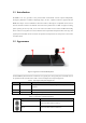
1.1 Introduction DS-1600KI is the new generation of fully touch-enabled and detachable network keyboard independently developed by Hikvision. In addition to displaying images, the 10.1" capacitive touchscreen supports DVI and HDMI video outputs. It runs on Android 4.4 and has the brand new UI design. It is compatible with all series of front-end and back-end devices of Hikvision and control center platform such as iVMS.
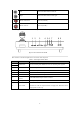
Left PTZ control mode: Move the PTZ left. Right PTZ control mode: Move the PTZ right. Rotate anticlockwise Zoom out (ZOOM-) Rotate clockwise Zoom in (ZOOM+) There are eight interfaces and one button on the rear panel of DS-1600KI keyboard. 1 2 3 4 56 7 DVI LIN E IN AUDIO OUT LAN 8 9 12 VDC POWER Figure 1.2 Rear Panel of DS-1600KI Refer to Table 1.3 for the description of the rear interface of the keyboard. Table 1.
Chapter 2 Getting Started 10
The network keyboard is in inactive status when it leaves factory. You should activate it before performing other operations. Then you can log in to and log out of the keyboard. 2.1 Activating the Keyboard For the first-time access, you need to activate the keyboard by setting an admin password. No operation is allowed before activation. You can activate by the local keyboard or SADP. Refer to Chapter 2.2 Configuring Keyboard by SADP for details. Steps: 1.
lower case letters, or numbers and upper case letters. A minimum of 8 characters are used. Figure 2.4 Medium Password Level 3 (Strong password): It includes three kinds of characters or above. A minimum of 8 characters are used. Figure 2.5 Strong Password 2. Confirm the password in the Confirm text field. 3. Click Activate button to activate the keyboard. 2.2 Configuring Keyboard by SADP You can also configure the keyboard by SADP.
Figure 2.7 Activating the Device 2. Enter the new password in the New Password text field and confirm the password in the Confirm Password text field. Figure 2.8 Entering and Confirming the Password The strength level of the password shows when you enter the password.
Figure 2.9 Modifying Network Parameters 3. Enter the Admin Password you have configured. 4. Click Modify button to complete the modification. You can modify the port randomly within the range from 2000 to 65535. You don’t need to modify the parameters of IPv6 Address, IPv6 Gateway, IPv6 Prefix Length and HTTP Port. Resetting the Keyboard Password Purpose: You can reset the keyboard password by SADP. Steps: 1. Select the checkbox before the ID of the DS-1600KI keyboard. 2.
3. Click Export button to download the key request file. Set the file path in the pop-up window. Click Select Folder to save the device key request file on your PC. The exported key request file is XML file which is named as Device Serial No.-System Time. 4. Send the key request file to our technical engineers and the engineer will send you a key file back. 5. Select Import File radio button as the resetting mode. 6. Click 7.
3. Select the user account name by clicking 4. Enter the password of the account. . 5. (Optional) You can click the checkbox to select Remember Password to save the password. 6. Click Login. If the admin enters wrong password for 7 times, the password would be locked. If the operator enters wrong password for 5 times, the password would be locked. The times of entering wrong password by two users in 3 minutes will be overlapped.
Chapter 3 General Settings 17
Purpose: You can configure the general settings of the keyboard including network, language, time and other settings. After starting up, you can see the home page as follows, including time information (yy/mm/dd, week and current time ), keyboard information, general settings and keyboard operation. Figure 3.1 Home Page of the Keyboard Click on the home page for the general configuration of the keyboard. A window pops up as shown in Figure 3.2. Figure 3.
Figure 3.3 General Settings Interface Refer to Table 3.1 for the description of the General Settings interface. Table 3.1 Description of General Settings Interface Menu Descriptions Ethernet Support two network configuration modes: Static IP and DHCP.
Figure 3.4 Setting the Static IP Parameters Task 2: Configure DHCP Steps: 1) Click the DHCP enable button to to enable DHCP configuration. 2) Click the Details button to enter the Details interface shown in Figure 3.5 to gain the practical IP parameters. Figure 3.5 Details of DHCP You can not enable Static IP and DHCP at the same time. 3.2 WLAN Settings Purpose: You can configure WLAN parameters to connect to the network. Steps: 1.
Figure 3.6 WLAN Configuration Interface 3. Connect to the network in two ways. Task 1: Connect to the available network in the list Steps: 1) Click the Wi-Fi hotspot in the Wi-Fi list 2) Enter the password and connect to the network. Figure 3.7 Connecting to Available Network Task 2: Add new network Steps: 1) Click the Add Network at the bottom of the Wi-Fi list. 2) Enter the SSID manually. Figure 3.
3) Select the security type as shown in Figure 3.9. Figure 3.9 Selecting the Security Type 4) Enter the password to connect to the network. If you open both the Ethernet and WLAN, the WLAN takes effect by default. 3.3 Language Settings Purpose: You can choose language for the device in this section. Steps: 1. Click the Language button on the right of the General interface to enter the Language Configuration interface. 2. Click the radio button to to select the Chinese or English language.
Configure Date & Time: Steps: 1. Click the Date & Time button on the right of the General interface to enter the configuration interface. Figure 3.11 Date and Time Configuration Interface 2. Set the date and time in two ways. Task 1: Automatic mode Steps: Enable the automatic mode by switching Task 2: Manual mode to , or else the manual mode is enabled. Steps: 1) Click to set the current date as shown in Figure 3.12. 2) Click to set the current time as shown in Figure 3.12. Figure 3.
Figure 3.13 Selecting Time Zone 3.5 Others Purpose: You can adjust the brightness of the screen, choose interval of the sleep time, enable/disable the alarm sound and choose the resolution of the external monitor. Steps: 1. Click the Others button on the right of the General interface to enter the configuration interface. Figure 3.14 Others Configuration Interface 2. Configure the other parameters. Task 1: Configure brightness Steps: Click to lighten the screen and click to darken the screen.
Steps: Click for interval selecting and five modes of interval are selectable. The pop-up window is shown in Figure 3.15. Figure 3.15 Selecting Sleeping Interval Task 3: Configure alarm sound Steps: Turn the alarm sound as ON via setting as and turn it as OFF via setting Support alarm in network disconnected, IP conflicted, USB error and FTP error conditions. as . Task 4: Configure the resolution of external monitor Steps: Click to select the resolution of external monitor.
Figure 3.
Chapter 4 Keyboard Application 27
4.1 Main Menu Click to enter the keyboard operation interface. You can click on the upper-right corner to enter the main menu shown in Figure 4.1. Figure 4.1 Main Menu Refer to Table 4.1 for the description of the main menu. Table 4.1 Description of Main Menu Menu Description Live view by Local/Video Wall/External, PTZ control, recording, picture capturing, Live View two-way audio, etc. Display device list, manage the device/camera/group/video wall, view device information, Device etc.
4.2 for the description of device management. Table 4.2 Description of Device Management Menu Description Device Add/view/delete/modify/refresh devices Camera View and modify the details of the channels. Group Add/delete/modify the groups which contains several channels. Video Wall Edit the video wall name, row and column; Configure the output of the channels on video wall. 4.2.
Figure 4.3 Device Management Interface of the Operator Adding a Device by the Admin Purpose: As the admin, you need to add a device firstly that all operations such as live view and device management are accessible. Two ways are available for adding the devices: manual adding and auto-adding. As an operator, you cannot add devices. All the devices authorized by the admin are shown on the Device Management interface. Up to 2000 devices can be added by the admin. Task1: Manual Adding Steps: 1.
Special characters are not allowed to enter. The longest length is 32 characters long. If the name is left empty, the current name of the device is remained. Type: The type of the added device. It is not editable when you add a device. The type of the device will be shown after you add it successfully. Address: The IP address of the added device. Port: The port of the added device. User Name: Enter the user name of the added device. Password: Enter the password of the added device. 2.
4. Enter the user name and password of the added device. 5. Click Confirm. 6. (Optional) You can click Cancel to cancel the auto-adding. When you add devices in batch, the user names and passwords of all the devices will be matched one by one. Only when matched successfully can the device be added. Editing the Device by the Admin Purpose: In the Device Management interface, for the admin, you can view the details of, refresh and delete the added devices. You can also clear all the added devices.
Figure 4.9 Editing the Device 3. Click to confirm the modification. 4. (Optional) You can click to cancel the modification. Refreshing the Device You can click Refresh to refresh the status of the added devices. Deleting the Device Steps: 1. Click Delete to delete the selected device. A hint box will pop up as shown in Figure.4.10 . Figure 4.10 Hint Box of Deleting the Device 2. Click Delete to confirm the deletion. 3. (Optional) You can click to cancel the deletion.
3. (Optional) You can click to cancel the deletion. Controlling the Front Panel of Added DVR/NVR by the Admin Purpose: The keyboard can control the front panel of the added DVR/NVR. Steps: 1. Click the added DVR/NVR in the Device Management interface. A pop-up box is shown in Figure 4.12. Figure 4.12 Editing the Added DVR/NVR 2. Select Control to enter the Remote Panel. Figure 4.13 DVR/NVR Remote Panel 3. Click the buttons on the control panel to control the front panel of the added DVR/NVR. 4.
Editing the Device by the Operator Purpose: In the Device Management interface, for the operator, you can only view the details of the added device and refresh it. Click the added device in the Device Management interface. A pop-up box is shown in Figure 4.14. Figure 4.14 Editing the Device Viewing the Device Steps: Click Details to view the detailed information of the added devices including IP address, port, etc. The details of the added devices are shown in Figure 4.15. Figure 4.
Figure 4.16 Editing the Added DVR/NVR by the Operator 2. Select Control to enter the DVR/NVR Control Panel. Figure 4.17 DVR/NVR Control Panel 3. Click the buttons on the control panel to control the front panel of the added DVR/NVR. 4. Click to exit from the DVR/NVR Control Panel. You can also view the details of, and refresh the added DVR/NVR. Refer to Editing the Device by the Operator for reference. 4.2.
Figure 4.18 Camera Management Interface The number on the upper-right corner of each camera, e.g., , is the serial number of the corresponding camera. Viewing the Camera Steps: 1. Click the camera tab to view the details. A window of channel details is shown in Figure 4.19. Figure 4.
Figure 4.20 Viewing the Camera for the Operator 2. You can view the information of the camera including name, channel ID, protocol, stream, device, address and channel No. Name: The name of the camera as desired. Channel ID: The serial number of the camera according to the added sequence. Protocol: The transfer protocol of the camera. Stream: The stream type of the camera. Device: The name of the channel. Address: The IP address and port of the corresponding device. Channel No.
When editing Name and Channel ID, you can click The range of the Channel ID is from 1 to 999999, and the ID cannot be repeated. 2. Click to delete the original information. to select the protocol. Figure 4.22 Selecting the Protocol 3. Click to select the stream. Figure 4.23 Selecting the Stream Type 4. Click to confirm the modification. 5. (Optional) You can click to cancel the modification. 4.2.
Figure 4.24 Group Management Interface Creating a New Group Purpose: You can create a new group and add some cameras in it. Steps: 1. Click New Group to manually create a group. A pop-up window is shown in Figure 4.25. Figure 4.25 Creating a New Group Name: Edit a name for the group as desired. Special characters are not allowed to enter in the Name text field. The longest length of the name is 32 characters long. Group No.: Edit the group number as desired. The range is from 1 to 16, and the No.
You can click The Dwell Time should be between 10s and 10000s. It is 30s by default. 2. to delete the original information. Click Add Camera to add channels into the new group. Figure 4.26 Adding Camera(s) to the New Group 3. Select the camera(s) by clicking 4. Click 5. (Optional) You can click and then click to go back to the New Group dialog box. to confirm the adding. to cancel the adding.
Figure 4.28 Viewing the Group 1. Click to modify the details of the selected group. Only Name, Dwell Time and Channels are editable. Figure 4.29 Modifying the Group 2. 3. If you want to delete an added camera, click . Click Add Camera to add camera(s) to the group. 4. Click 5. (Optional) You can click to confirm the modification. to cancel the modification. Deleting the Group Steps: 1. Click Delete to delete the selected group. A hint box will pop up as follows. Figure 4.
3. (Optional) You can click to cancel the deletion. Clearing the Groups Steps: 1. Click Clear to delete all the groups. A hint box will pop up as follows. Figure 4.31 Hint Box of Deleting all the Groups 2. Click Delete to confirm the deletion. 3. (Optional) You can click to cancel the deletion. 4.2.
You can edit the details of the video wall, including the name, row and column. Steps: 1. Click on the upper-right corner. A window pops up as shown in Figure 4.33. Figure 4.33 Editing the Video Wall Name: Edit a name for the video wall as desired. Row: The row of the video wall. Column: The column of the video wall. You can click The row and column should be between 1 and 8. The details will be displayed on the upper-left corner. 2. Click 3.
Figure 4.34 Selecting the Output Channel 2. Click on the upper-left corner to view all the channels of the decoder. 3. Click one of the channels to set it as the output channel of the selected window. 4. (Optional) You can click to cancel the configuration. Deleting the Configured Window As the admin, hold down the configured window for one second. Click on the upper-right corner of the selected window to delete it. Figure 4.
opening/closing the window, moving the window and switching the images and groups. The multi-screen display configured on the iVMS-5200 client software cannot be deleted by holding down the window and clicking . 4.3 Live View For the admin and operators, the live view steps are the same. This section takes the operations of the admin as an example. Purpose: After the device is successfully added, you can view the live video of the added network cameras and video encoders in the Live View interface.
Figure 4.37 Selecting Live View Types Refer to Table 4.3 for the description of the live view mode. Table 4.3 Description of Live View Mode Menu Description Local Live view of the added devices locally on the touchscreen of the keyboard. Video Wall Live view of the added devices on the video wall. External Live view of the added devices via the external devices. 4.3.
Figure 4.39 Local Live View Interface Refer to Table 4.4 for the description of the live view icons. Table 4.4 Description of Live View Icons Icon Description Select the window division. The screen will be displayed in 1-division mode by default. The window division modes vary with the connected devices. PTZ control panel. Stop all the live view. Capture picture of the selected live view window, and save the picture to the USB disk or upload it to the FTP server.
Refer to Table 4.5 for the description of the live view numeric panel icons. Table 4.5 Description of Live View Numeric Panel Icons Icon 0~9 Description Number 0 to 9. Delete the entered information. View the live video of the added cameras. View the live video of the added groups. View the previous/next camera or group. Starting Live View Steps: 1. (Optional) You can click in the upper-left corner to set the window division mode as desired. Click to select the window division mode. Figure 4.
then select multi-window division mode. Figure 4.42 Hint box of Starting Auto-Switch of the Group (1) Figure 4.43 Hint box of Starting Auto-Switch of the Group (2) 4. Enter 0 in the numeric panel and click . You can stop the live view of the corresponding camera. 5. (Optional) You can click to delete the entered information if you entered incorrectly. 6. (Optional) You can click or 7. (Optional) You can double-click the selected window to realize full-screen live view.
The PTZ control should be supported by the added device. You can turn the joystick to realize the pan left/right and tilt up/down movements. You can also rotate the joystick anticlockwise/clockwise to zoom out/in in the live view. Refer to Table 4.6 for the description of PTZ control panel icons. Table 4.6 Description of PTZ Control Panel Icons Icon Description Set and call the preset. Call the patrol. Start/stop the auto-scan. Call and record the pattern.
2. Slide to select a patrol No. in the dialog box and click Call to call it. The patrol No. should be between 1 and 32. 3. Click Cancel to close the patrol dialog box. Recording and Calling a Pattern Patterns can be set to record the movement of the PTZ. Steps: 1. In the PTZ control mode, click to access the dialog box shown in Figure 4.47. Figure 4.47 Setting a Pattern 2. Slide to select a pattern No. in the dialog box. 3. Click Record to start recording of this pattern path.
Recording Steps: 1. Select one output window and enter the serial number in the numeric panel, and then click . The live video of the corresponding cameras will be displayed on the selected window. 2. Click to record the video of the selected window, and then the icon will change to . The hint of “Start recording” will appear. 3. Click to stop recording and the hint of “Stop recording” will appear.
Figure 4.50 Live View Interface of Video Wall You can edit the name of the video wall as well as the row and column in Video Wall Management interface. Refer to Chapter 4.2.4 Managing the Video Wall for details. Refer to Table 4.7 for the description of video wall icons. Table 4.7 Description of Video Wall Icons Icon Description Select the window division mode. The window division modes vary with the connected devices. PTZ control panel. Call the scene of the video wall.
Figure 4.51 Live View Numeric Panel Refer to Table 4.8 for the description of video wall numeric panel icons. Table 4.8 Description of Video Wall Numeric Panel Icons Icon 0~9 Description Number 0 to 9. Delete the entered information. View the live video of the added cameras. View the live video of the added groups. View the previous/next camera or group. Starting Live View Steps: 1. (Optional) You can click Click 2. on the upper-left corner to set the video wall window division as desired.
The PTZ control should be supported by the added device. You can turn the joystick to realize the pan left/right and tilt up/down movements. You can also rotate the joystick anticlockwise/clockwise to zoom out/in in the live view. Refer to Chapter 4.3.1 Local View for details. Switching the Scene Steps: 1. Select one output window and enter the serial number in the numeric panel, and then click . The live video of the corresponding cameras will be displayed on the selected window. 2.
Recording Steps: 1. Select one output window and enter the serial number in the numeric panel, and then click . The live video of the corresponding cameras will be displayed on the selected window. 2. Click to record the video of the selected window, and then the icon will change to . The hint of “Start recording” will appear. 3. Click to stop recording and the hint of “Stop recording” will appear.
Figure 4.53 Floating the Window 3. During moving the window, the dotted borders will display. You can double-click the window to adjust it to match it to the borders. Figure 4.54 Matching the Window Closing the Window Steps: 1. Hold down the window to access the 2. Hold down the window again to hide the button on the window by which you can close the window. button.
Figure 4.55 Closing the Window 4.3.3 External View Purpose: The keyboard supports external preview of the live video of the added devices, e.g., external display via HDMI or DVI interface. The local keyboard will not display the video. Select External in the pop-up window of live view mode. Figure 4.56 Selecting External Live View Figure 4.
Refer to Table 4.9 for the description of the external live view icons. Table 4.9 Description of External Live View Icons Icon Description Select the window division mode. The screen will be displayed in 1-division mode by default. The window division modes vary with the connected devices. PTZ control panel. Stop all the live view. Capture picture of the selected live view window, and upload the picture to the USB disk or to the FTP server.
to select the window division mode. 2. Select one output window and enter the serial number in the numeric panel, and then click . The live view of the corresponding cameras will be displayed on the selected window. 3. Select one output window and enter the serial number, then click group will be displayed on the selected window. . The live view of the corresponding For group, auto-switching is only supported in single-screen mode. 4. Enter 0 in the numeric panel and click 5.
2. Click to record the video of the selected window, and then the icon will change to . The hint of “Start recording” will appear. 3. Click to stop recording and the hint of “Stop recording” will appear. You must connect a USB disk to the keyboard, or ensure the network connection of the PC (running FTP server) and the keyboard is valid and correct. Run the FTP server on the PC and copy the firmware into the corresponding directory of your PC. Two-Way Audio Steps: 1.
including viewing/deleting user accounts, adding devices to the users and changing the password. For the operator, you can only view the account and change the password. The keyboard supports adding 1 admin and 15 operators at most. The admin has the highest authority and can operate the devices. The operators can only operate the devices linked by the admin. Select User on the right side to enter the User Management interface. Figure 4.59 User Management Interface for the Admin Figure 4.
Adding a New User by the Admin Only the admin can add new users. Steps: 1. Click New User in the User Management interface for the admin to open the New User dialog box. Figure 4.61 Adding a New User 2. Enter the user name, password and confirm password as desired.
Figure 4.62 Adding Device(s) to the New User Only the devices which have already been added to the admin account will be displayed in the device list. 4. Select the device(s) by clicking and then click 5. If you want to delete a certain device, click 6. Click 7. (Optional) You can click to go back to the New User dialog box. . to confirm the creation. to cancel the adding.
Figure 4.64. Figure 4.64 Editing the Normal User Account 2. Click Details to edit the detailed information of the user account including password and related devices. The details of the user account are shown in Figure 4.65. Figure 4.65 Viewing the User Detailed Information 3. Click to set the password Figure 4.66 Setting the Password 4. Enter the New Password and confirm the password. 5. Click Submit to confirm the edit. 6. (Optional) You can click 7.
Figure 4.67 Adding Device(s) to the User Only the devices which have already been added to the admin account will be displayed in the device list. 8. Select the device(s) by clicking 9. If you want to delete a certain device, click 10. Click and then click to go back to the User Details dialog box. . to confirm the editing. 11. (Optional) You can click to cancel the editing. Deleting the User Accounts by the Admin Steps: 1. Click Delete to delete the selected user.
2. Click Delete to confirm the deletion. 3. (Optional) You can click to cancel the deletion. Editing the User Accounts by the Operator Steps: 1. Click the user account on the User Management interface for the operator. The Set Password dialog box pops up as shown in Figure 4.70. Figure 4.70 Editing the User Account by the Operator 2. You can change the old password by entering the Old Password, New Password and confirming the password. 3. Click 4.
1. Click on the upper-right corner of the User Management interface for the operator to logout. Figure 4.72 Logout Interface for the Operator 2. Click Confirm to logout. 3. (Optional) Click to cancel the operation. 4.4.2 Storage Management Purpose: You can configure the FTP server parameters in Storage Management interface. In Live View mode, you can upload captured pictures and records to the FTP server. Otherwise you can save them to the USB disk.
Figure 4.74 Storage Management Interface for the Operator 2. 3. Switch on the upper-right corner to . Enter the Address, Folder, User Name and Password of the FTP server. Figure 4.75 Configuring FTP Server You can create a new folder in the root directory of the user. 4. Click Apply. 4.4.3 System Maintenance This section is only applicable to the admin. Purpose: You can upgrade the system, import and export the configuration files, and restore the defaults of local configurations.
Figure 4.76 System Maintenance Interface Upgrade: When there is a new version available in the USB disk, you can click Browse to select the upgrade patch to update the system. Import: You can import the configuration file from the USB disk. Export: You can export the configuration file to the USB disk. Simple Restore: You can restore the defaults of local configurations expect the network parameters and the admin password.
Chapter 5 Accessing by iVMS Platform 72
DS-1600KI Network Keyboard can be accessed by iVMS-5200. You should make proper configuration on the iVMS platform before connecting the keyboard to the iVMS server. Refer to the user manual of corresponding iVMS platform for instructions. 5.1 Configuring iVMS-5200 Platform 5.1.1 Platform Login Click on the home page to enter the Platform Login interface. Figure 5.1 Platform Login Steps: 1. Enter the IP address, Port, User Name and Password of the accessed platform. 2.
Figure 5.2 Main Menu of Platform Configuration Refer to Table 5.1 for the description of the main menu. Table 5.1 Description of Main Menu Menu Description Video Wall Display the live video of the input channel on the output monitor of the video wall. Resource Display the resource list. Logout Log out of the platform module. 5.1.3 Managing the Video Wall After logging in to the platform, you should select the video wall first. Click on the main menu to enter the Resource List interface.
Figure 5.3 Resource List of Video Wall The number on the upper-right corner of each item stands for the serial number of the video wall. Click a video wall to enter the Scene List interface. Figure 5.4 Scene List Steps: 1. Call the scene by clicking 2. Click . to exit from the Scene List interface and return to the Resource List interface. After calling the scene of the video wall, appears on the right-bottom corner of the selected video wall item, indicating that the video wall is in use. 3.
4. Log in to the iVMS 5200 and click Live View to view the screen layout. Figure 5.6 Screen Layout Interface 5.1.4 Managing the Input Channel Steps: 1. Click or on the Resource List interface to expand the input channel list under the selected tab. The number on the upper-right corner stands for the serial number of the input channel. Figure 5.7 Resource List of Input Channel The input channel list of each level contains at most 512 input channels. 2. Click to return to the resource list. 3.
Click Logical View->Camera to enter the following interface to view the list of connected input channels: Figure 5.8 Camera List Select an input channel from the list and click it to enter the Editing interface to modify the index No. in the Keyboard No. field. Figure 5.9 Editing Camera Interface If you do not configure the serial number, you can not operate on the keyboard. The configuration method varies with different platforms. 5.
2. Enter the monitor number in the text field to display the video of the selected camera on the selected monitor directly. Task 2: Click on the main menu to enter the Video Wall interface. Figure 5.11 Video Wall Interface stands for the video wall you have configured in the resource list of video wall. Refer to Chapter 5.1.3 Managing the Video Wall for details. There is a numeric panel on the right with numbers 0 to 9 and five other icons for you to enter the serial number of the device. Figure 5.
Preview the live video of the input channel. Preview the live video of the input channel on the selected output monitor of the video wall. Preview the previous/next input channel. You can follow the steps as follows to view the video of an input channel on the selected monitor. Steps: 1. Enter the serial number of the output monitor in the numeric panel, and click 2. Enter the serial number of the input channel in the numeric panel, and click . .
1. Click on the main menu and a window box pops up as follows. Figure 5.14 Logout Interface 2. Click Confirm to log out of the Platform module. 3. (Optional) You can click to cancel the logout.
Chapter 6 Accessing by Matrix Access Gateway 81
Purpose: You can get access to the matrix access gateway, realize unified management of the monitors, switch the live video on the video wall and set PTZ control on the Matrix module. The PTZ control should be supported by the added device. 6.1 Matrix Access Gateway Login Click on the home page to enter the Matrix Access Gateway Login interface. Figure 6.1 Matrix Access Gateway Login Interface Steps: 1. Enter the IP address, Port, User Name and Password of the matrix. 2.
Refer to Table 5.3 for the description of video wall numeric panel icons. Table 5.3 Description of Video Wall Numeric Panel Icons Icon 0~9 Description Number 0 to 9. Delete the entered information. Preview the live video of the input channel. Preview the live video of the input channel on the selected output monitor of the video wall. Preview the previous/next input channel. You can follow the steps as follows to view the video of an input channel on the selected monitor. Steps: 1.
6.3 Logout Steps: 1. Click on the upper-right corner of the Video Wall interface and a window box pops up as follows. Figure 6.4 Logout Interface 2. Click Confirm to log out of the Matrix module. 3. (Optional) You can click to cancel the logout.
Chapter 7 Appendix 85
7.1 Specifications Model DS-1600KI Operating System Android 4.4 10.1" TFT LCD touchscreen TFT LCD Screen Resolution: 1024 × 600 Joystick 4-axis joystick Local Decoding Local decoding 2-ch at up to 1080p resolution , and up to 16-division window display Two-way Audio 1-ch, 3.5 mm connector Input (2.0Vp-p, >10kΩ) Audio Output 1-ch, 3.5 mm connector (2.0 Vp-p, 600 Ω) Network Interface 1 10M/100M/1000M self-adaptive Ethernet interface WiFi Supported USB Interface USB 2.
87