HD-TVI Speed Dome Quick Start Guide
HD-TVI Speed Dome·Quick Start Guide Quick Start Guide COPYRIGHT © 2018 Hangzhou Hikvision Digital Technology Co., Ltd. ALL RIGHTS RESERVED. Any and all information, including, among others, wordings, pictures, graphs are the properties of Hangzhou Hikvision Digital Technology Co., Ltd. or its subsidiaries (hereinafter referred to be “Hikvision”).
HD-TVI Speed Dome·Quick Start Guide environment. This equipment generates, uses, and can radiate radio frequency energy and, if not installed and used in accordance with the instruction manual, may cause harmful interference to radio communications. Operation of this equipment in a residential area is likely to cause harmful interference in which case the user will be required to correct the interference at his own expense. FCC Conditions This device complies with part 15 of the FCC Rules.
HD-TVI Speed Dome·Quick Start Guide Safety Instruction These instructions are intended to ensure that user can use the product correctly to avoid danger or property loss. The precaution measure is divided into “Warnings” and “Cautions” Warnings: Serious injury or death may occur if any of the warnings are neglected. Cautions: Injury or equipment damage may occur if any of the cautions are neglected. Warnings Follow these safeguards to prevent serious injury or death.
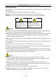
HD-TVI Speed Dome·Quick Start Guide Do not aim the speed dome at the sun or extra bright places. A blooming or smear may occur otherwise (which is not a malfunction however), and affecting the endurance of sensor at the same time. Please use the provided glove when open up the dome cover, avoid direct contact with the dome cover, because the acidic sweat of the fingers may erode the surface coating of the dome cover.
HD-TVI Speed Dome·Quick Start Guide Table of Contents 1 Installation ................................................................................................... 1 1.1 Connecting the Cables .............................................................................................................. 1 1.2 DIP Switch Settings ................................................................................................................... 2 1.2.1 Mini Speed Dome Settings ............................
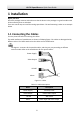
HD-TVI Speed Dome·Quick Start Guide 1 Installation Before you start: Check the package contents and make sure that the device in the package is in good condition and all the assembly parts are included. There are several ways to install the analog speed dome. The wall mounting is taken as an example below. 1.1 Connecting the Cables Turn the power off before connecting the cables. The cable interfaces of speed dome are shown in following figure. The cables are distinguished by different colors.
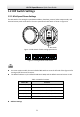
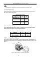
HD-TVI Speed Dome·Quick Start Guide 1.2 DIP Switch Settings 1.2.1 Mini Speed Dome Settings The DIP switch is for setting the speed dome address, baudrate, protocol, video output mode, and terminal resistor, with value OFF=0. The mini speed dome’s DIP switch is shown in Figure1-2.
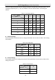
HD-TVI Speed Dome·Quick Start Guide The No.1 to No.5 DIP switches are for setting the address of speed dome, with value ON=1, 2, 3, 4, 5 standing respectively for 1, 2, 4, 8, 16, and OFF=0. You can refer to Table 1-3 for setting the address. Table 1-3 Set Dome Address Switch Dome Address 1 2 3 4 5 0 OFF OFF OFF OFF OFF 1 ON OFF OFF OFF OFF 2 OFF ON OFF OFF OFF 3 ON ON OFF OFF OFF 4 OFF OFF ON OFF OFF … … … … … … 31 ON ON ON ON ON Baudrate Settings The No.
HD-TVI Speed Dome·Quick Start Guide The speed dome is self-adaptive to private protocol when the No.8 switch is OFF. Video Output Settings The No.10 DIP switch is for setting the video output mode of the speed dome. You can refer to Table 1-6 for setting the video output. Table 1-6 Set Video Output Switch No. Video Output 9 10 TVI OFF OFF AHD ON OFF CVI OFF ON CVBS ON ON Terminal Resistor Settings The two individual DIP switches, No.1 and No.
HD-TVI Speed Dome·Quick Start Guide DIP Switch 1234567 8 12 Figure 1-5 DIP Switch for 5-inch Indoor Speed Dome Figure 1-6 Enlarged View of DIP Switch The default address is 0. The default baudrate is 2400. Table 1-8 Switch Functions Switch No. Function 1 to 5 Set the address for the speed dome 6 to 7 Set the baudrate for the speed dome 8 Set the protocol for the speed dome 1 to 2 (Right) Set the video output mode for the speed dome Address Settings The No.1 to No.
HD-TVI Speed Dome·Quick Start Guide Switch No. Dome Address 1 2 3 4 5 … … … … … … 31 ON ON ON ON ON Baudrate Settings The No.6 and No.7 DIP switches are for setting the baudrate of the speed dome. The baudrate can be 2400bps, 4800bps, 9600bps, or 19200bps. The baudrate will be set as 2400bps by default when it is out of this range. Refer to the following table for details Table 1-10 Set Baudrate Switch No.
HD-TVI Speed Dome·Quick Start Guide Table 1-12 Set Video Output Switch No. Video Output 1 2 TVI OFF OFF AHD ON OFF CVI OFF ON CVBS ON ON 1.2.3 Mini IR & 5-inch IR Speed Dome Settings The DIP switch is used for setting the speed dome address, baudrate, protocol, video output mode, and terminal resistor, with value OFF=0. DIP switch of mini IR speed dome is shown in figure1-7, and the DIP switch of 5-inch IR speed dome is shown in figure1-8.
HD-TVI Speed Dome·Quick Start Guide ON 1 DIP 2 3 4 5 6 7 8 9 10 Figure 1-9 Enlarged View of DIP Switch The default address is 0, the default baudrate is 2400, and the default terminal resistor is OFF. Table 1-13 Switch Functions Switch No.
HD-TVI Speed Dome·Quick Start Guide Table 1-15 Set Baudrate Switch No. 6 Baudrate 2400 OFF 9600 ON Protocol Settings The No.7 DIP switch is for setting the protocol. Refer to the following table for setting the protocol. Table 1-16 Set Protocol Protocol 7 Self-adaptive OFF MAN_AD ON The speed dome is self-adaptive to private protocol when the No.7 switch is OFF. Video Output Settings The No.8 and No.9 DIP switches are for setting the video output mode of the speed dome.
HD-TVI Speed Dome·Quick Start Guide Table 1-18 Set Terminal Resistor Switch No. Description 10 Turn on the resistor ON Turn off the resistor OFF 1.2.4 7-inch IR Speed Dome Settings Two DIP switches, SW1 and SW2, are for setting the speed dome address, baudrate, protocol, video output mode, and terminal resistor, with value OFF=0. The DIP switch of the speed dome is shown as Figure 1-10.
HD-TVI Speed Dome·Quick Start Guide Address Settings The SW1 switch is used for setting the address of speed dome, with value ON=1, 2, 3, 4, 5, 6, 7 standing respectively for 1, 2, 4, 8, 16, 32, 64, 128, and OFF=0. You can refer to the Table 1-20 for setting the address.
HD-TVI Speed Dome·Quick Start Guide DIP Switch SW2-Protocol Settings HIKVISION ON ON OFF KALATE OFF OFF ON VICON ON OFF ON MAN_BOSCH OFF ON ON MAN_AD ON ON ON Video Output Settings The No.6, No.7 SW2 switches are for setting the video output mode of the speed dome. You can refer to Table 1-23 for setting the video output. Table 1-23 Set Video Output Switch No. 6 7 TVI OFF OFF AHD ON OFF CVI OFF ON CVBS ON ON Description Terminal Resistor Settings The No.
HD-TVI Speed Dome·Quick Start Guide surrounding, electromagnetic interference, etc.. Choose the cable with nominal voltage higher than the actual voltage to guarantee a normal running. To protect the power cable and the signal transmitting cable from human tampering, you should pay attention to the protection and reinforcement of the cables. When wiring, do not tighten the wire or loosen the wire. The wiring of the speed dome should be performed by professionals. 1.3.
HD-TVI Speed Dome·Quick Start Guide Figure 1-14 Secure the Mount 5. Install the speed dome to the mount. Refer to Section 1.3.4 Installing the Speed Dome for installation details. Follow the same instructions described above for the short-arm wall mount. For outdoor applications, adopt the water-proof measures. The short-arm wall mount is not recommended for outdoor applications. 1.3.3 Setting the DIP Switch Set the address and baudrate for the speed dome.
HD-TVI Speed Dome·Quick Start Guide ① ② ③ Figure 1-15 Install the Speed Dome 15
HD-TVI Speed Dome·Quick Start Guide 2 In-door Mounting Applications Before you start: For the cement wall, you need to use the expansion screw to fix the mount. The mounting hole of the expansion pipe on the wall should align with the mounting hole on the mount. For the wooden wall, you can just use the self-tapping screw to fix the mount. 2.1 5-inch Speed Dome In-ceiling Mounting Applications Before you start: The in-ceiling mounting is applicable to the indoor ceiling construction.
HD-TVI Speed Dome·Quick Start Guide Figure 2-2 Draw and Cut Hole on the Ceiling 6. Connect the cables. (1) Make sure the video cable and control wire have been connected to the corresponding interface. (2) Connect the power cable, and the red LED indicator turns on when the power is on. Turn the power off after checking the speed dome. 7. Install the speed dome.
HD-TVI Speed Dome·Quick Start Guide 8. Install the trim ring. (1) Attach the trim ring to the lower dome and align the triangular notch of the trim ring with the arrow label on the in-ceiling mount. (2) After having firmly placed the trim ring to the ceiling, rotate the trim ring in the direction of arrow to secure the trim ring in place. Remove the protective film on the lower dome after the installation is finished.
HD-TVI Speed Dome·Quick Start Guide Figure 2-6 Remove 4 screws 2. Remove the in-ceiling mount. Figure 2-7 Remove the in-ceiling mounting mount 3. Screw 4 bolts onto the back box by a Phillips screwdriver. Figure 2-8 Install the bolts 2.2.2 Wiring The cables of dome can be routed either from the top or the side of the back box. For the cables routed from the top of the back box, it is required to drill a cable hole in the ceiling.
HD-TVI Speed Dome·Quick Start Guide Figure 2-9 Cabling for Ceiling Mounting 2.2.3 Ceiling Mounting Steps: 1. Rotate the lower dome counterclockwise to separate it from the back box. Refer to the Figure 21. 2. Remove the protective lens cover, foam and sticker from the dome drive. 3. Set the address and baudrate for the analog speed dome. Please refer to the Section 1.2.1 5inch Speed Dome Settings for DIP switch settings. 4. Attach lower dome to the back box, and rotate clockwise to secure it. 5.
HD-TVI Speed Dome·Quick Start Guide Screw Holes Cable Hole Figure 2-11 Secure the Mounting Base 8. Install the speed dome to the mounting base. (1) Route the cables for the speed dome. Align the bottom of the speed dome with the mounting base. (2) Line up the direction of arrow with the spring end of the mounting base. (3) Push the speed dome upwards and then forwards in the direction of arrow. When the speed dome is placed in position, the spring will automatically snap into the lock clip firmly.
HD-TVI Speed Dome·Quick Start Guide 2.3 Mini Speed Dome In-ceiling Mounting Applications Before you start: The in-ceiling mounting is applicable to the indoor ceiling construction. The followings are the mandatory precondition for mounting: The height of the space above the ceiling must be more than 250 mm. The ceiling must be with the thickness between 5 to 40 mm. The ceiling must be strong enough to withstand more than 4 times the weight of the dome and its accessories. Steps: 1.
HD-TVI Speed Dome·Quick Start Guide (4) Reinstall the toggles as shown in Figure 2-15. Toggle Bolt Figure 2-15 Install the Toggle Bolts 4. 5. 6. Align the toggle bolts with the screw holes on the ceiling. Push the dome to the mounting hole on the ceiling. Rotate the bolts again. The toggle will automatically rotate down to secure the dome to the ceiling. Ceiling Toggle Figure 2-16 Install the Dome to the Ceiling 7. Secure the lower dome to the back box with three screws as shown in Figure 2-17.
HD-TVI Speed Dome·Quick Start Guide 2.4 Mini Speed Dome Ceiling Mounting Applications Before you start: The ceiling mounting is applicable to the indoor/outdoor solid ceiling construction. The followings are the mandatory precondition for ceiling mounting: The ceiling must be with the thickness between 5 to 40 mm. The ceiling must be strong enough to withstand more than 4 times the weight of the dome and its accessories. 2.4.
HD-TVI Speed Dome·Quick Start Guide Protective Foam Notch Lower Dome Lens Cover Sticker Figure 2-20 Disassemble the Speed Dome 3. 4. Attach lower dome to the back box, and secure it with screws. Align the ceiling mount with the screw holes on the drill template. Secure the ceiling mount to the ceiling with screws (supplied). Ceiling Figure 2-21 Install Ceiling Mount 5. 6. Align the hook of the ceiling with unlock label on the speed dome.
HD-TVI Speed Dome·Quick Start Guide 3 Application and Operations 3.1 System Application The device can be controlled through the back-end device or control software. The back-end device includes control keyboard, DVR (Digital Video Recorder), etc., and the control software includes client software. Here we take the connection of DVR as the example.
HD-TVI Speed Dome·Quick Start Guide MAIN MENUS EXIT ENGLISH Figure 3-2 Main Menu Refer to the user manual for the detailed instruction to set the speed dome. 3.2.1 Configuring Patrol You can set the patrol function by the DVR and OSD menu, as well as the one-touch patrol can be realized. Configuring Patrol by DVR Steps: 1. Enter the PTZ Control interface. Menu > Camera > PTZ Figure 3-3 PTZ Settings 2.
HD-TVI Speed Dome·Quick Start Guide Figure 3-4 Key point Configuration 4. Configure key point parameters, such as the key point No., duration of staying for one key point and speed of patrol. The key point is corresponding to the preset. The Key Point No. determines the order at which the PTZ will follow while cycling through the patrol. The Duration refers to the time span to stay at the corresponding key point. The Speed defines the speed at which the PTZ will move from one key point to the next. 5.
HD-TVI Speed Dome·Quick Start Guide 3. Up to 8 patrols can be configured. Edit the patrol. (1) Move the cursor to EDIT PATROL and click IRIS+ to enter the editing mode. NUM PST DWELL SPEED 1 0 6 30 2 3 0 0 6 6 30 30 4 0 6 30 5 0 6 30 6 0 6 30 7 0 IRIS+ OK 6 30 IRIS- CANCEL Figure 3-6 Edit the Patrol (2) (3) 4. Click up/down direction buttons to choose the number and locate the preset to be edited.
HD-TVI Speed Dome·Quick Start Guide 3.2.2 Configuring Park Actions Purpose: For some certain model of the speed dome, it can be configured to start a predefined park action (scan, preset, patrol and etc.) automatically after a period of inactivity (park time). Configuring Park Actions by DVR Steps: 1. Click the PTZ in the lower-right corner of the PTZ setting interface. Menu > Camera > PTZ 2. Click the button to show the one-touch function of the PTZ control. Figure 3-7 PTZ Panel - One-touch 3.
HD-TVI Speed Dome·Quick Start Guide MOTION AUTO FLIP ON PROPORTIONAL PAN ON PARK TIME PARK ACT 5 NONE SCAN SPEED IMAGE FREEZE 28 OFF DOME SPEED BACK 6 EXIT Figure 3-8 PTZ Configuration 2. 3. Move the cursor to the PARK TIME, and set the value ranging from 5 to 720 seconds. Move the cursor to the PARK ACT, and the action can be set as preset 1 to 8, pattern 1 to 5, patrol 1 to 10, pan scan, tilt scan, random scan, frame scan, panoramic scan, day mode, night mode, patrol-d or none.
HD-TVI Speed Dome·Quick Start Guide 4 Troubleshooting 4.1 Device Exceptions Question Why does the speed dome fail to start or repeatedly reboot? Why does the speed dome restart intermittently when controlling PTZ, calling presets or turning on the infrared lights of the IR dome at night? Answer Check the supply voltage of the dome. Ensure the supply voltage to meet the power requirements of the speed dome. The nearest power supply is recommended.
HD-TVI Speed Dome·Quick Start Guide Answer Please check whether the protective film of the bubble has been removed. Please check whether there are foreign objects on the bubble or the lens. Please check where there are obstructions such as spider web nearby. Open the bubble and check whether the lens cover has been removed. Restore the device to the default settings. Call the preset 95 to enter the OSD menu and select the RESTORE CAMERA.
HD-TVI Speed Dome·Quick Start Guide UD08995B 34