i HD-TVI Speed Dome User Manual HD-TVI Speed Dome User Manual UD03862B
ii HD-TVI Speed Dome User Manual User Manual © 2016 Hangzhou Hikvision Digital Technology Co., Ltd. This user manual is intended for users of HD-TVI Speed Dome. It includes instructions on how to use the Product. The software embodied in the Product is governed by the user license agreement covering that Product. About this Manual This Manual is subject to domestic and international copyright protection. Hangzhou Hikvision Digital Technology Co., Ltd. (“Hikvision”) reserves all rights to this manual.
iii HD-TVI Speed Dome User Manual Regulatory Information FCC Information Please take attention that changes or modification not expressly approved by the party responsible for compliance could void the user’s authority to operate the equipment. FCC compliance: This equipment has been tested and found to comply with the limits for a Class A digital device, pursuant to part 15 of the FCC Rules.
iv HD-TVI Speed Dome User Manual Safety Instruction These instructions are intended to ensure that the user can use the product correctly to avoid danger or property loss. The precaution measure is divided into ‘Warnings’ and ‘Cautions’: Warnings: Serious injury or death may be caused if any of these warnings are neglected. Cautions: Injury or equipment damage may be caused if any of these cautions are neglected.
v HD-TVI Speed Dome User Manual Cautions: Make sure the power supply voltage is correct before using the product. Do not drop the product or subject it to physical shock. Do not install the product on vibratory surface or places. Do not expose it to high electromagnetic radiating environment. Do not aim the lens at the strong light such as sun or incandescent lamp. The strong light can cause fatal damage to the product.
vi HD-TVI Speed Dome User Manual Table of Contents Chapter 1 1.1 1.2 Description ............................................................................................................................... 1 Functions .................................................................................................................................. 1 Chapter 2 2.1 2.2 2.3 2.4 Overview ..................................................................................................................
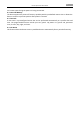
1 HD-TVI Speed Dome User Manual Chapter 1 Overview 1.1 Description Integrated with the built-in pan/tilt unit, the HD-TVI speed dome features highly sensitive response and reliable performance. The speed dome can be adopted in various surveillance fields with its full-integral functions and features, such as corridor, large venue, meeting room, station, neighborhoods, etc. 1.2 Functions The functions vary according to the different models of the speed dome.
2 HD-TVI Speed Dome User Manual In manual tracking mode, when a target object goes directly beneath the dome, the video will automatically flips 180 degrees in horizontal direction to maintain continuity of tracking. This function can also be realized by auto mirror image depending on different camera models. Privacy Mask This function allows you to block or mask certain area of a scene, for preventing the personal privacy from recording or live viewing.
3 HD-TVI Speed Dome User Manual are in auto status during the pattern is being memorized. Power Off Memory The dome supports the power off memory capability with the predefined resume time. It allows the dome to resume its previous position after power is restored. Time Task A time task is a preconfigured action that can be performed automatically at a specific date and time. The programmable actions include: pan scan, patrol 1-8, pattern 1-4, preset 1-8, panorama scan, tilt scan, day, night, and none.
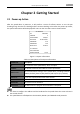
4 HD-TVI Speed Dome User Manual Chapter 2 Getting Started 2.1 Power-up Action After the speed dome is power-on, it will perform a series of self-test actions. It runs the pan checking firstly, then the tilt checking and the camera checking at last. After the power-up actions, the system information will be displayed for 120 s on the live view screen as shown below. XX-XXXXX-XX SN XXXXXXXX ADDRESS 0 COM FORMAT 2400,8,1 PROTOCOL AUTO MATCH FIRMWARE X.XX HARDWARE X.
5 HD-TVI Speed Dome User Manual 2.2 Basic Operations You can operate the speed dome by using a control device, including the control keyboard, DVR, DVS, etc. In this manual, accessing the speed dome via the web browser will be taken as the example. Panning and tilting: Click the direction buttons to control the pan and tilt movement of the speed dome. Zooming: Click the ZOOM+ and ZOOM- buttons to control the zooming. Focusing: Click the FOCUS+ and FOCUS- buttons to adjust the focus.
6 HD-TVI Speed Dome User Manual 2.4 On-screen Displays The speed dome supports following on-screen displays: Zoom Ratio: Identifies the amount of magnification. The format is ZXXX. XXX is the zoom amount. PT Angle: Displays panning and tilting direction, with the format of NEXXX/TXXX. The NE followed with XXX indicates the degrees in north east direction, while the T followed with XXX indicates the degrees in tilt position. Alarm: When an alarm is triggered, the corresponding information will be displayed.
7 HD-TVI Speed Dome User Manual Chapter 3 Menu Operation The operation interface of the different speed domes may differ. Please refer to the actual operation interface. You can click the left and right direction buttons in the PTZ control panel via the web browser of the DVR to enter the next page or return to the previous page of the submenu if more than one page is available.
8 HD-TVI Speed Dome User Manual 3.1 Accessing and Operating the Menu To enter the main menu: Steps: 1. Connect the video and RS-485 cables of speed dome to a DVR. 2. Visit the DVR via the web browser. 3. View the live video of the speed dome. 4. For PELCO-P/D and other private PTZ protocols, call preset 95 from the preset list in the PTZ control panel of the DVR.
9 HD-TVI Speed Dome User Manual model, address, protocol, etc. The information shown on this submenu is similar to the system information shown after the power-up action. Please refer to Section 2.1 for more details. Enter the system information display menu: MAIN MENUS > SYSTEM INFO SYS INFO XX-XXXXX-X 0 ADDRESS COM FORMAT PROTOCOL VERSION HARDVERSION BUILD DATE BACK 2400,8,1 SELF ADAPTIVE 1.00 1.00 16 11 04 EXIT SYS INFO CAM VERSION PARAM DATE TEMPERATURE TRACK TRACKBUILDTIM BACK X.XX X XX XX 38 X.
10 HD-TVI Speed Dome User Manual Dome address settings To Set the Soft Address of the Speed Dome If the SET SOFT ADDR ACT is set as ON, the soft address is the valid address for connecting the speed dome. The selectable soft address ranges from 1 to 255; If the SET SOFT ADDR ACT is set as OFF, the hard address set by the DIP switch is the valid address of the speed dome. Before you set the soft address of the speed dome, you need to confirm that it is within the control range of the control device (e.
11 HD-TVI Speed Dome User Manual Y- M- D 16 12 12 H- M- S 15 33 25 DONE: OPEN QUIR: CLOSE Figure 3-5 Set the System Time Zero Angle Configuration Purpose: You can define the zero angle of the speed dome on the ZERO ANGLE submenu. Steps: 1. Move the cursor to ZERO ANGLE using the direction buttons and click IRIS+ to enter. 2. Click the left/right/up/down direction buttons to adjust the monitor angle of the speed dome. 3. Click IRIS+ button to confirm the settings and exit.
12 HD-TVI Speed Dome User Manual DISPLAY SETTINGS ZOOM SHOW P/T SHOW ALARM SHOW TIME SHOW PRESET SHOW ON ON OFF ON ON ZONE SHOW ADDRESS SHOW OFF OFF BACK EXIT DISPLAY SETTINGS ERROR RATE FAN/HEAT BACK OFF OFF EXIT Figure 3-6 Display Settings The speed dome shows the viewing direction when you manually control it to rotate.
13 HD-TVI Speed Dome User Manual Enable the RS-485 configuration diagnosis. You can set 485 CHECK as ON or AUTO for automatic RS-485 configuration diagnosis. If the configuration is incorrect, an alert will be received; if you set the value as AUTO, it will automatically stop the diagnosis when no errors exist. Power Memory Settings The dome can resume its previous PTZ status after it restarted from a power-off when it stops at a position longer than the predefined time.
14 HD-TVI Speed Dome User Manual CAMERA WHITE BALAN RED BLUE IMAGE FLIP FOCUS LIMIT 2D DNR ATW 64 64 OFF 1M 1 3D DNR 2 BACK EXIT CAMERA CAMERA WIDE LIMIT CHROMA SUPPRESS SATURATION 2.0 1 1 GAIN LIMIT DEFOG 15 OFF INIT LENS OFF CONTRAST OFF SCENE MODE INDOOR HLC ON SHARPNESS COMP 15 BACK EXIT BACK EXIT Figure 3-7 Camera Settings Task 1: Configure the focus settings. Setting the focus mode Steps: 1. Move the cursor to FOCUS using the direction buttons and click IRIS+ to enter. 2.
15 HD-TVI Speed Dome User Manual If you set the ZOOM LIMIT as the minimum value 22, the digital zoom function will be disabled, and the optical zoom function is at its maximum value. Configure the zoom speed. Purpose: You can define the speed at which the lens changes from full wide zoom to the optical zoom. Steps: 1. Move the cursor to ZOOM SPEED using the direction buttons and click IRIS+ to enter. 2. Click up/down direction buttons to choose the speed from HIGH (default), MEDUIM and LOW. 3.
16 HD-TVI Speed Dome User Manual (2) BLC LEVEL. You can manually adjust the backlight compensation level. Task 6: Configuring the iris, gain and shutter speed Set the Exposure Mode Purpose: AE mode defines the priority of iris, shutter and gain while the speed dome adjusting the brightness of the live view. You can change the mode on AE MODE submenu. AUTO: Auto iris, auto shutter and auto gain. The speed dome adjusts the values automatically responding to the lighting conditions. It is the default mode.
17 HD-TVI Speed Dome User Manual The value of X indicates that the shutter speed is 1/X second. If you set the SHUTTER value bigger (shutter speed is faster), the amount of entering light per second is fewer, and the image is darker. (2) Slow shutter. Set SLOW SHUTTER as ON, the shutter speed can automatically slow down to extend exposure time under low lighting circumstances to obtain clearer image. Task 7: Configure exposure compensation. You can set the EXPOSURE COMP value from 0 to 14.
18 HD-TVI Speed Dome User Manual Task 12: Configure the image quality. Wide Limit Set the value of WIDE LIMIT to limit the minimum zoom of the lens with 1.0, 1.1, 1.2, 1.3, 1.5, 1.8 and 2.0 available. The Wide Limit function is supported by certain speed dome model series. Chroma Suppress Set the Chroma suppress value from 1 to 3 to suppress the color noise so as to get the clear and high-quality image in the low luminance environment.
19 HD-TVI Speed Dome User Manual When there is fog in the image, you can enable this function to get clear image. Task 14: Configure the lens initialization. You can turn INIT LENS on to trigger a spontaneous lens initiation to ensure the normal operation. 3.3.2 Configuring Privacy Mask Purpose: Focus limit enables you to cover certain areas on the live video from being live viewed and recorded.
20 HD-TVI Speed Dome User Manual ADJUST BLANK POS FOCUS SHIFT STATUS SAVE: OPEN QUIT: CLOSE Figure 3-9 Set the Privacy Mask (2) You can see ADJUST BLANK POS message on the screen. Click the direction buttons to adjust the position of the privacy blank to the designed scene. (3) Click FOCUS+ button, and you can see ADJUST BLANK SIZE message on the screen. Click the up/down buttons to increase/decrease the height of the mask and click right/left buttons to increase/decrease the width of the mask.
21 HD-TVI Speed Dome User Manual 3.3.4 Configuring IR Parameters The IR parameter settings are supported by IR speed domes only. Purpose: You can configure the IR parameters including the IR sensitivity, n/m LED current, far LED current, reference zoom, and LED control, fan control, switch delay, smart IR, etc..
22 HD-TVI Speed Dome User Manual 3.4 Configuring PTZ Control Parameters Purpose: You can configure panning, tilting and zooming movements, and configure PTZ control functions including presets, patrols, patterns, etc. for the speed dome. 3.4.
23 HD-TVI Speed Dome User Manual If no control signal is received after the park time under the following circumstances, no park actions will be performed: in the process of performing dome actions by calling special presets; or in the process of performing external alarm linkage actions. Image freeze This feature enables the live view to switch directly from the current scene to another scene that is defined by a preset, without showing the middle areas between these two scenes.
24 HD-TVI Speed Dome User Manual Elevation set You can set the SET ELEVATION as ON to increase the elevation angle range of the speed dome or set it as OFF to disable the function. The range of the elevation angle varies from different speed dome models. 3.4.2 Configuring Presets Purpose: A preset is a user-defined monitoring position/point. You can simply call the preset number to change the monitor scene to the defined position. Steps: 1.
25 HD-TVI Speed Dome User Manual You can select the preset number from the drop-down preset list in the control panel of the encoder through a web browser, and click the arrow to call a user-defined or system-defined preset. 5. Clear the preset settings. Move the cursor to CLEAR and click IRIS+ to clear the settings of the current preset. 3.4.3 Configuring Patrols Purpose: A patrol is a scanning track specified by a group of user-defined presets.
26 HD-TVI Speed Dome User Manual NUM PST 1 0 2 0 3 0 4 0 5 0 6 0 7 0 DONE: OPEN DWELL 6 6 6 6 6 6 6 SPD 30 30 30 30 30 30 30 QUIT: CLOSE Figure 3-14 Edit the Patrol (2) Click up/down direction buttons to choose the number and locate the preset to be edited. (3) Click left/right direction buttons to position the cursor to the column of PRESET, DWELL and SPEED. You can click the up/down direction buttons to set the value of preset number, dwell time and patrol speed. 4. 5. 6. 7.
27 HD-TVI Speed Dome User Manual and power-up). Steps: 1. Move the cursor to enter the PATTERNS submenu: MAIN MENU > DOME SETTINGS > PATTERNS PATTERNS PATTERN NUM RECORD PATTERN PREVIEW CLEAR PATTERN REMAINING BACK 1 100 EXIT Figure 3-15 Pattern Configuration Menu 2. Choose the pattern number. (1) Move the cursor to PATTERN NUM and click IRIS+ to enter the editing mode. (2) Click the up/down direction buttons to select the number of the pattern which is to be configured.
28 HD-TVI Speed Dome User Manual remaining memory shown under PATTERNS menu as REMAINING. The pan/tilt movements and the lens operations cannot be memorized simultaneously. 4. Preview the pattern. Enter the PREVIEW menu to preview the current pattern. 5. Call the defined pattern. You can call the special presets to call the defined pattern. E.g. call preset 41 to call pattern 1. Please refer to Section 2.2 to find the corresponding preset number for each pattern. 6. Delete the patterns.
29 HD-TVI Speed Dome User Manual Up to 8 time tasks can be configured. 3. Set the task status. Steps: (1) Move the cursor to ENABLE TASK and click IRIS+ to enter the editing mode. (2) Click the up/down direction buttons to set the task status as ON. (3) Click IRIS+ again to confirm the settings and exit the editing mode of this column. If the task action and task time have not been configured, you cannot set the status as ON. 4. Configure the task action.
30 HD-TVI Speed Dome User Manual 3.4.6 Configuring Zone Purpose: A zone is a panning and tilting area defined by the left/right limits. You can configure the zones on ZONES submenu. You can define a zone when the targeted surveillance scene is limited. Steps: 1. Move the cursor to enter the zone configuration submenu: MAIN MENU > DOME SETTINGS > ZONES ZONES ZONE NUM 1 EDIT ZONE ZONE STATUS SCAN STATUS CLEAR ZONE BACK ON ON EXIT Figure 3-19 Zone Configuration 2.
31 HD-TVI Speed Dome User Manual 3.4.7 Configuring Smart Settings Purpose: Set the smart settings as ON to automatically track the moving object, and meanwhile adjusts the focus and the position to set the target in the center of the field of view. Steps: 1. Move the cursor to enter the smart setting submenu: MAIN MENU > DOME SETTINGS > SMART SETTINGS SMART SETTING TRACK ACTIVE OFF TRACK TIME 100 TRACK ZOOMRATIO BACK EXIT Figure 3-20 Smart Setting 2. Set the tracking time.
32 HD-TVI Speed Dome User Manual CLEAR SETTINGS CLEAR ALL PRESETS CLEAR ALL PATROLS CLEAR ALL PATTERNS CLEAR ALL BLANKS CLEAR ALL ZONES CLEAR ALL TIME TASK DIAGNOSTICSE BACK EXIT Figure 3-21 CLEAR SETTINGS 2. Move the cursor to the item you want to clear, and click IRIS+ to validate the settings. 3. Move the cursor to the DIAGNOSTICS and click IRIS+ to diagnose the temperature exception, video exception, voltage exception, etc. The function varies according to the different camera models. 3.
33 HD-TVI Speed Dome User Manual 2. Choose the alarm number. Steps: (1) Move the cursor to ALARM NUM and click the IRIS+ to enter the editing mode. (2) Click the up and down direction buttons to select the number of the alarm which is to be configured. (3) Click IRIS+ again to confirm and exit editing mode of this column. You can configure up to 2 alarm inputs. 3. Move the cursor to ALARM SETTING and click the IRIS+ to enter the setting alarm submenu. 4. Configure the alarm input.
34 HD-TVI Speed Dome User Manual 2. Configure the interval of the alarm sequence. When more than one alarm of the same priority occurs at the same time, the speed dome will respond to one alarm first and then respond to the next one after the user-defined interval. You can set the on SEQUENCE submenu from 1 to 200 seconds. 3. Configure the alarm rest delay.
35 HD-TVI Speed Dome User Manual (1) Enter MAIN MENUS > DOME SETTINGS > ALARMS > ALARM SETTING and choose the alarm number that you want to link the alarm output to. (2) Move the cursor to AUXS and click IRIS+ to configure the alarm output to the alarm. You can choose OPEN to active AUX 1. 3.6 Others 3.6.1 Restoring Default Dome Settings Purpose: You can reset all dome settings to factory default parameters as shown in below.
36 HD-TVI Speed Dome User Manual Appendix Appendix 1 Lightning & Surge Protection This product adopts TVS plate lightning protection technology to avoid damage caused by pulse signal that is below 3000W, like instantaneous lighting stroke, surging, etc. According to the actual outdoor situation, necessary protection measures must be taken, besides ensuring the electrical safety. The distance between signal transmission wires and High-voltage equipment or high-voltage cable is at least 50m.
37 HD-TVI Speed Dome User Manual Appendix 2 RS485 Bus Connection General Property of RS485 Bus According to RS485 industry bus standard, RS485 is a half-duplex communication bus which has 120Ω characteristic impendence, the maximum load ability is 32 payloads (including controller device and controlled device). RS485 Bus Transmission Distance When using 0.56mm (24AWG) twisted-pair line, according to different baudrate, the maximum transmission distance theory table is shown as below: Table A-1 Max.
38 HD-TVI Speed Dome User Manual 1# 6# Controller 32# 15# Figure A-4 Star Shape Connection For such case, the best way is adding a RS485 distributor. This product can effectively change the star-shape connection to which satisfies the requirement of RS485 industry standard, in order to avoid those problems and improve the communication reliability. Show as figure 5.
39 HD-TVI Speed Dome User Manual Problem dome can be controlled but not smoothly. Possible Reasons To Solve the Problem tightly. 2. RS485+ or RS485-wire is 2. Change a RS485 wire. broken. 3. The speed dome is too far away 3. Add a terminal resistor. from the remote control device. 4. Too many speed domes are 4. Add a RS485 distributor. connected.
40 HD-TVI Speed Dome User Manual Appendix 3 24VAC Wire Gauge & Transmission Distance The following table describes the recommended Max. distance adopted for the certain wire gauge when the loss rate of 24VAC voltage is less than 10%. For the AC driven device, the maximum voltage loss rate is 10% allowable. For example, for a device with the rating power of 80VA which is installed at a distance of 35 feet (10m) away from the transformer, then 0.8000mm is required as the minimum wire gauge.
41 HD-TVI Speed Dome User Manual Appendix 4 Wire Gauge Standards Bare Wire Gauge(mm) 0.750 0.800 0.900 1.000 1.250 1.500 2.000 2.500 3.000 American Wire Gauge AWG 21 20 19 18 16 15 12 British Wire Gauge SWG 21 20 19 18 17 14 Cross-sectional Area of Bare Wire(mm2) 0.4417 0.5027 0.6362 0.7854 1.2266 1.7663 3.1420 4.9080 7.
42 HD-TVI Speed Dome User Manual