
User Manual
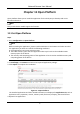
Table Of Contents
- Chapter 1 System Requirement
- Chapter 2 Device Activation and Accessing
- Chapter 3 Live View
- 3.1 Live View Parameters
- 3.1.1 Enable and Disable Live View
- 3.1.2 Adjust Aspect Ratio
- 3.1.3 Live View Stream Type
- 3.1.4 Select the Third-Party Plug-in
- 3.1.5 Light
- 3.1.6 Count Pixel
- 3.1.7 Start Digital Zoom
- 3.1.8 Auxiliary Focus
- 3.1.9 Lens Initialization
- 3.1.10 Quick Set Live View
- 3.1.11 Lens Parameters Adjustment
- 3.1.12 Conduct 3D Positioning
- 3.2 Set Transmission Parameters
- 3.3 Set Smooth Streaming
- 3.1 Live View Parameters
- Chapter 4 Video and Audio
- Chapter 5 Video Recording and Picture Capture
- Chapter 6 Event and Alarm
- 6.1 Basic Event
- 6.2 Smart Event
- 6.2.1 Detect Audio Exception
- 6.2.2 Set Defocus Detection
- 6.2.3 Detect Scene Change
- 6.2.4 Set Face Detection
- 6.2.5 Set Video Loss
- 6.2.6 Set Intrusion Detection
- 6.2.7 Set Line Crossing Detection
- 6.2.8 Set Region Entrance Detection
- 6.2.9 Set Region Exiting Detection
- 6.2.10 Set Unattended Baggage Detection
- 6.2.11 Set Object Removal Detection
- 6.2.12 Draw Area
- 6.2.13 Set Size Filter
- Chapter 7 Network Settings
- Chapter 8 Arming Schedule and Alarm Linkage
- Chapter 9 System and Security
- 9.1 View Device Information
- 9.2 Search and Manage Log
- 9.3 Simultaneous Login
- 9.4 Import and Export Configuration File
- 9.5 Export Diagnose Information
- 9.6 Reboot
- 9.7 Restore and Default
- 9.8 Upgrade
- 9.9 View Open Source Software License
- 9.10 Wiegand
- 9.11 Metadata
- 9.12 Time and Date
- 9.13 Set RS-485
- 9.14 Set RS-232
- 9.15 Power Consumption Mode
- 9.16 External Device
- 9.17 Security
- 9.18 Certificate Management
- 9.19 User and Account
- Chapter 10 Allocate VCA Resource
- Chapter 11 Open Platform
- Chapter 12 Smart Display
- Chapter 13 Set EPTZ
- Chapter 14 Pattern Linkage
- A. Device Command
- B. Device Communication Matrix

Network Camera User Manual
108
Max. Capture Interval
The max. interval between two captures when the target is in the detection area. The camera
takes the capture when it reaches the max. interval even if the face grading does not reach the set
threshold.
Quick Setup Mode
Select the mode according to actual using scenarios. In custom mode, you can set Comparison
Timeout and Comparison Times.
8. Set arming schedule. See Set Arming Schedule.
9. Set linkage method. See Linkage Method Settings.
View Face Comparison Result
Steps
1. Go to Application.
2. Set search condition and click Counting.
Matched results are shown in Face Picture Comparison Statistics area.
10.9.2 Face Modeling
Face modeling serves the purpose of collecting face pictures, creating face models and uploading
data to the surveillance center.
Before You Start
Face Capture or Multi-Target-Type detection should be configured for face picture collection. See
Face Capture or Multi-Target-Type Detection for configuration instructions.
Steps
1. Go to Configuration → Comparison and Modeling → Face Comparison and Modeling.
2. Select Face Modeling to start.
3. Check Enable Face Modeling.
4. Set parameters for modeling.
Report Face Modeling Information in Multi-Target-Type Capture Alarm
When a person triggers the multi-target-type detection, the alarm information includes the
face modeling information of the detected face if checked.
Quick Capture
The device starts face modeling when it detects a face which scores higher than the set face
grading threshold for capture.
Face Grading Threshold for Capture
The face grading threshold for the device to judge whether to capture and upload the face or