Network Bullet Camera Quick Start Guide UD04310B 0
Network Bullet Camera·Quick Start Guide Quick Start Guide COPYRIGHT © 2017 Hangzhou Hikvision Digital Technology Co., Ltd. ALL RIGHTS RESERVED. Any and all information, including, among others, wordings, pictures, graphs are the properties of Hangzhou Hikvision Digital Technology Co., Ltd. or its subsidiaries (hereinafter referred to be “Hikvision”).
Network Bullet Camera·Quick Start Guide Legal Disclaimer TO THE MAXIMUM EXTENT PERMITTED BY APPLICABLE LAW, THE PRODUCT DESCRIBED, WITH ITS HARDWARE, SOFTWARE AND FIRMWARE, IS PROVIDED “AS IS”, WITH ALL FAULTS AND ERRORS, AND HIKVISION MAKES NO WARRANTIES, EXPRESS OR IMPLIED, INCLUDING WITHOUT LIMITATION, MERCHANTABILITY, SATISFACTORY QUALITY, FITNESS FOR A PARTICULAR PURPOSE, AND NON-INFRINGEMENT OF THIRD PARTY.
Network Bullet Camera·Quick Start Guide IN THE EVENT OF ANY CONFLICTS BETWEEN THIS MANUAL AND THE APPLICABLE LAW, THE LATER PREVAILS. Regulatory Information FCC Information Please take attention that changes or modification not expressly approved by the party responsible for compliance could void the user’s authority to operate the equipment. FCC compliance: This equipment has been tested and found to comply with the limits for a Class B digital device, pursuant to part 15 of the FCC Rules.
Network Bullet Camera·Quick Start Guide This device complies with part 15 of the FCC Rules. Operation is subject to the following two conditions: 1. This device may not cause harmful interference. 2. This device must accept any interference received, including interference that may cause undesired operation.
Network Bullet Camera·Quick Start Guide Industry Canada ICES-003 Compliance This device meets the CAN ICES-3 (B)/NMB-3(B) standards requirements. Safety Instruction These instructions are intended to ensure that user can use the product correctly to avoid danger or property loss. The precaution measure is divided into “Warnings” and “Cautions” Warnings: Serious injury or death may occur if any of the warnings are neglected.
Network Bullet Camera·Quick Start Guide ● Input voltage should meet both the SELV (Safety Extra Low Voltage) and the Limited Power Source with 24 VAC or 12 VDC according to the IEC60950-1 standard. Please refer to technical specifications for detailed information. ● Do not connect several devices to one power adapter as adapter overload may cause over-heating or a fire hazard. ● Please make sure that the plug is firmly connected to the power socket.
Network Bullet Camera·Quick Start Guide ● The sensor may be burned out by a laser beam, so when any laser equipment is in using, make sure that the surface of sensor will not be exposed to the laser beam. ● Do not place the camera in extremely hot, cold (the operating temperature shall be-30°C ~+60°C, or -40°C ~ +60°C if the camera model has an “H” in its suffix), dusty or damp locations, and do not expose it to high electromagnetic radiation.
Network Bullet Camera·Quick Start Guide Table of Contents 1 Appearance Description ................................................................. 9 1.1 Camera Overview ............................................................ 9 1.2 Cable Description .......................................................... 10 2 Installation .................................................................................... 13 2.1 Memory Card Installation .............................................. 14 2.
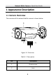
Network Bullet Camera·Quick Start Guide 1 Appearance Description 1.1 Camera Overview The overview of the network bullet camera is shown below. 3 4 2 1 5 7 6 Figure 1-1 Overview Table 1-1 Description No.
Network Bullet Camera·Quick Start Guide No. Description 3 Sun Shield 4 3-axis Bracket 5 Reset Button 6 Memory Card Slot 7 Serial Port The standard power supply is 12V DC, please make sure your power supply matches with your camera. Press RESET about 10s when the camera is powering on or rebooting to restore the default settings, including the user name, password, IP address, port No., etc. 1.
Network Bullet Camera·Quick Start Guide 1 2 3 4 5 6 7 Figure 1-2 Cable and Interface Overview Table 1-2 Cable and Interface Description No.
Network Bullet Camera·Quick Start Guide No.
Network Bullet Camera·Quick Start Guide 2 Installation Before you start: ● Make sure the device in the package is in good condition and all the assembly parts are included. ● The standard power supply is 12V DC, please make sure your power supply matches with your camera. ● Make sure all the related equipment is power-off during the installation. ● Check the specification of the products for the installation environment.
Network Bullet Camera·Quick Start Guide 2.1 Memory Card Installation This series of camera supports memory card installation. Please follow the steps below to install the micro SD card. 1. Loosen the two lock screws at the bottom of the bullet camera, and then remove the slot cover. Slot Cover Figure 2-1 Remove Card Cover 2. Insert the memory card into the memory card slot.
Network Bullet Camera·Quick Start Guide 3. (Optional) To unmount the memory card, push the inserted memory card to get it ejected. 4. Screw the slot cover back to complete the installation. 2.2 Direct Mounting Before you start: Bullet cameras of this series are equipped with an integrative mounting bracket. You can mount the camera directly on wall or ceiling. Steps: 1. Past the drill template to the desired mounting place of wall or ceiling.
Network Bullet Camera·Quick Start Guide 2. Drill the screw holes according to the Screw Hole 1. (Optional) If you want to route cables through the wall or ceiling, cut a hole according to Hole A of the drill template. Insert the expansion screws first if the camera is mounted to the cement wall or ceiling. And you can use the self-tapping screws directly if camera is mounted to the wooden ceiling. 3. Route the cables and fix the camera to the ceiling or wall with the supplied screws.
Network Bullet Camera·Quick Start Guide It is recommended to adopt the water-proof jacket (supplied) for the network interface when the camera is installed outdoor. See Section 2.5. 4. Adjust the surveillance angle with supplied wrench. 1). Loosen No.1 lock screw to adjust the tilt angle [0 ° to 100°]. 2). Loosen No.2 lock screw to adjust the pan angle [0° to 360°]. 3). Loosen No.3 lock screw to rotate the camera [0° to 360°]. 4). Tighten the lock screws.
Network Bullet Camera·Quick Start Guide 2.3 Wall Mounting with a Junction Box Before you start: A junction box is not included in the package. If you choose this mounting type, you have to prepare a junction box in advance. Note that the size and screw holes of a junction box should match those of the camera. Figure 2-7 Bracket Bottom Overview Steps: 1. Paste the drill template on the desired mounting place on wall. 2. Drill the screw holes for the junction box according to Hole 2 of the drill template.
Network Bullet Camera·Quick Start Guide 4. Route the cables. 5. Fix the camera to the junction box with screws. 6. Adjust the surveillance angle. See step 4 in Section 2.2. 7. Install the water-proof jacket. See Section 2.5. Screw Hole 2 Wall Drill Template Junction Box Camera Bracket Figure 2-8 Installation with a Junction Box 2.4 Wall Mounting with a Gang Box Before you start: If you choose this mounting type, you have to prepare a gang box and an adapter plate in advance.
Network Bullet Camera·Quick Start Guide Steps: 1. Install the adapter plate to the gang box. 2. Route the cables. 3. Fix the camera to the adapter plate with screws. 4. Adjust the surveillance angle. See step 4 in Section 2.2. 5. Install the water-proof jacket. See Section 2.5. Gang Box Adapter Plate Camera Bracket Figure 2-9 Installation with a Gang Box 2.
Network Bullet Camera·Quick Start Guide ① ② ③ ④ ⑤ ⑥ ⑦ Figure 2-10 Water-proof Accessory Components Table 2-1 Components No. Components 1 Camera’s Network Interface Socket 2 O-Type Gasket 3 Network Plug 4 Waterproof Endcap 5 Waterproof Rubber Gasket 6 Lock Nut 7 Network Cable from Router/Switch Steps: 1.
Network Bullet Camera·Quick Start Guide 3. Place the O-type gasket ② onto the end of the camera’s network interface socket ①. 4. Insert the network plug ③ into the camera’s network interface socket①. 5. Insert the waterproof rubber gasket ⑤ into the waterproof endcap ④, and secure lock nut ⑥ with the waterproof endcap ④. 6.
Network Bullet Camera·Quick Start Guide 3 Setting the Network Camera over the LAN Note: You shall acknowledge that the use of the product with Internet access might be under network security risks. For avoidance of any network attacks and information leakage, please strengthen your own protection. If the product does not work properly, contact your dealer or the nearest service center for help. 3.1 Wiring Connect the camera to network according to the following figures.
Network Bullet Camera·Quick Start Guide 3.2 Activating the Camera You are required to activate the camera first by setting a strong password for it before you can use the camera. Activation via Web Browser, Activation via SADP, and Activation via Client Software are all supported. We will take activation via SADP software and Activation via Web Browser as examples to introduce the camera activation. Note: Refer to the User Manual of Network Camera for Activation via Client Software. 3.2.
Network Bullet Camera·Quick Start Guide Figure 3-3 Activation Interface(Web) 3. Create a password and input the password into the password field. STRONG PASSWORD RECOMMENDED– We highly recommend you create a strong password of your own choosing (using a minimum of 8 characters, including upper case letters, lower case letters, numbers, and special characters) in order to increase the security of your product.
Network Bullet Camera·Quick Start Guide Get the SADP software from the supplied disk or the official website, and install the SADP according to the prompts. Follow the steps to activate the camera. Steps: 1. Run the SADP software to search the online devices. 2. Check the device status from the device list, and select the inactive device. Select inactive device. Input and confirm password. Figure 3-4 SADP Interface Note: The SADP software supports activating the camera in batch.
Network Bullet Camera·Quick Start Guide STRONG PASSWORD RECOMMENDED– We highly recommend you create a strong password of your own choosing (using a minimum of 8 characters, including upper case letters, lower case letters, numbers, and special characters) in order to increase the security of your product. And we recommend you reset your password regularly, especially in the high security system, resetting the password monthly or weekly can better protect your product.
Network Bullet Camera·Quick Start Guide Steps: 1. Run the SADP software. 2. Select an active device. 3. Change the device IP address to the same subnet with your computer by either modifying the IP address manually or checking the checkbox of Enable DHCP.
Network Bullet Camera·Quick Start Guide Note: You can enable the Hik-Connect service for the device during activation. Refer to Chapter 5.1 for detailed information. 4. Input the admin password and click Modify to activate your IP address modification. The batch IP address modification is supported by the SADP. Refer to the user manual of SADP for details.
Network Bullet Camera·Quick Start Guide 4 Accessing via Web Browser System Requirement: Operating System: Microsoft Windows XP SP1 and above version CPU: 2.0 GHz or higher RAM: 1G or higher Display: 1024×768 resolution or higher Web Browser: Internet Explorer 8.0 and above version, Apple Safari 5.0.2 and above version, Mozilla Firefox 5.0 and above version and Google Chrome 18 and above version Steps: 1. Open the web browser. 2.
Network Bullet Camera·Quick Start Guide 4. Click Login. Figure 4-1 Login Interface 5. Install the plug-in before viewing the live video and managing the camera. Follow the installation prompts to install the plug-in. Note: You may have to close the web browser to finish the installation of the plug-in. Figure 4-2 Download Plug-in 6. Reopen the web browser after the installation of the plug-in and repeat steps 2 to 4 to login.
Network Bullet Camera·Quick Start Guide 5 Operating via Hik-Connect App Purpose: Hik-Connect is an application for mobile devices. With the App, you can view live image of the camera, receive alarm notification and so on. Note: Hik-Connect service is not supported by certain camera models. 5.1 Enable Hik-Connect Service on Camera Purpose: Hik-Connect service should be enabled on your camera before using the service. You can enable the service through SADP software or web browser. 5.1.
Network Bullet Camera·Quick Start Guide Figure 5-1 Verification Code Setting (SADP) Note: The verification code is required when you add the camera to Hik-Connect app. 3. Click and read "Terms of Service" and "Privacy Policy". 4. Confirm the settings. 5.1.2 Enable Hik-Connect Service via Web Browser Before you start: You need to activate the camera before enabling the service. Refer to Chapter 3.2.
Network Bullet Camera·Quick Start Guide Steps: 1. Access the camera via web browser. Refer to Chapter 4. 2. Enter platform access configuration interface: Configuration > Network > Advanced Settings > Platform Access Figure 5-2 Platform Access Configuration (Web) 3. Select Platform Access Mode as Hik-Connect. 4. Check the checkbox of Enable. 5. Click and read "Terms of Service" and "Privacy Policy" in pop-up window. 6. Create a verification code or change the verification code for the camera.
Network Bullet Camera·Quick Start Guide 5.2 Hik-Connect Setup Steps: 1. Download and install the Hik-Connect app by searching “Hik-Connect” in App Store or Google PlayTM. 2. Launch the app and register for a Hik-Connect user account. 3. Log in Hik-Connect app after registration. 5.3 Adding Camera to Hik-Connect Before you start: You need to enable the Hik-Connect service on camera before adding it to your Hik-Connect account. Refer to Chapter 5.1. Steps: 1.
Network Bullet Camera·Quick Start Guide You can find the QR code on the camera or on the cover of the Quick Start Guide of the camera in the package. Figure 5-4 Scan QR Code Note: If the QR code is missing or too blur to be recognized, you can also add the camera by tapping the icon and inputting the camera's serial number. 3. Input the verification code of your camera. Note: ● The required verification code is the code you create or change when you enabling Hik-Connect service on camera.
Network Bullet Camera·Quick Start Guide 5.4 Initializing the Memory Card Steps: Check the memory card status by tapping on the Storage Status in the Device Settings interface. If the memory card status displays as Uninitialized, tap to initialize it. The status will then change to Normal. You can then start recording any event triggered video in the camera such as motion detection.
0