TURBO HD TVI Bullet & Turret Camera User Manual User Manual Thank you for purchasing our product. If there are any questions, or requests, do not hesitate to contact the dealer. This manual applies to the model listed below. Type Model Type I DS-2CE16D0T-IT1E/3E/5E Type II DS-2CE16D0T-IRE/IRPE Type III DS-2CE56D0T-IT1E/3E This manual may contain several technically incorrect places or printing errors, and the content is subject to change without notice.
Regulatory Information FCC Information FCC compliance: This equipment has been tested and found to comply with the limits for a Class A digital device, pursuant to part 15 of the FCC Rules. These limits are designed to provide reasonable protection against harmful interference when the equipment is operated in a commercial environment.
Safety Instruction These instructions are intended to ensure that user can use the product correctly to avoid danger or property loss. The precaution measure is divided into “Warnings” and “Cautions” Warnings: Serious injury or death may occur if any of the warnings are neglected. Cautions: Injury or equipment damage may occur if any of the cautions are neglected. Warnings Follow these safeguards to prevent serious injury or death.
The sensor may be burned out by a laser beam, so when any laser equipment is in using, make sure that the surface of sensor will not be exposed to the laser beam. Do not place the camera in extremely hot, cold, dusty or damp locations, and do not expose it to high electromagnetic radiation. To avoid heat accumulation, good ventilation is required for operating environment. Keep the camera away from liquid while in use.
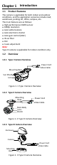
Introduction 1.1 Product Features The camera is applicable for both indoor and outdoor conditions, and the application scenarios include road, warehouse, parking lot, office, campus, etc.. The main features are as follows: High performance CMOS sensor 1080p resolution Auto white balance Auto electronic shutter Auto gain control (AGC) IR cut filter PoC 3-axis adjustment Note: Type III camera is applicable for indoor condition only. 1.2 Overview 1.2.
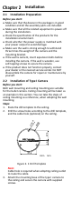
Installation 2.1 Installation Preparation Before you start: Make sure that the device in the package is in good condition and all the assembly parts are included. Make sure that all the related equipment is power-off during the installation. Check the specification of the products for the installation environment. Check whether the power supply is matched with your power output to avoid damage.
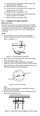
Figure 2. 2 Secure the Camera to the Ceiling Note: The supplied screw package contains self-tapping screws, and expansion bolts. For cement wall, expansion bolts are required to fix the camera. For wooden wall, self-tapping screws are required. 4. Route the cables through the cable hole (optional), or the side opening. 5. Connect the corresponding power cord, and video cable. 6. Power on the camera to check whether the image on the monitor is gotten from the optimum angle.
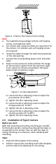
4 13.7 27.5 Φ6 8 3-Φ 47.6 3. Unit: mm Figure 2. 4 Drill Template Note: Cable hole is required when adopting ceiling outlet to route the cable. Attach the mounting base of the type I camera to the ceiling and secure the camera with supplied screws. Figure 2. 5 Secure the camera to the ceiling Note: The supplied screw package contains self-tapping screws, and expansion bolts. For cement wall, expansion bolts are required to fix the camera. For wooden wall, self-tapping screws are required. 4.
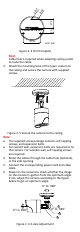
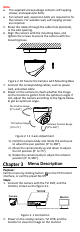
1). Loosen the No.1 adjusting screw to adjust the pan position (0° to 360°). 2). Tighten the No.1 adjusting screw. 3). Loosen the No.2 adjusting screw to adjust the tilting position (0° to 180°). 4). Tighten the No. 2 adjusting screw. 5). Loosen the No.3 adjusting screw to adjust the rotation position (0° to 360°). 6). Tighten the No.3 adjusting screw. 2.4 Installation of Type III camera Before you start: Both wall mounting and ceiling mounting are suitable for the turret camera.
Note: The supplied screw package contains self-tapping screws, and expansion bolts. For cement wall, expansion bolts are required to fix the camera. For wooden wall, self-tapping screws are required. 5. Route the cables through the cable hole (optional), or the side opening. 6. Align the camera with the mounting base, and tighten the screws to secure the camera with the mounting base. Figure 2. 10 Secure the Camera with Mounting Base 7.
3. Click PTZ Control to enter the PTZ Control interface. 4. Call the camera menu by clicking button, or call the preset No. 95. BRIGHTNESS AE EXPOSURE MODE AGC DWDR RETURN FORMAT MODE WB RETURN MODE LANGUAGE DAY-NIGHT INFRARED SMART IR RETURN IMAGE MODE MAIN MENU CONTRAST VIDEO SETTINGS SHARPNESS COLOR GAIN DNR MIRROR RETURN RESET SAVE & EXIT Figure 3. 2 Main Menu Overview 5. Click the direction arrow to control the camera. 7). Click up/down direction button to select the item. 8).
EXPOSURE BRIGHTNESS EXPOSURE MODE AGC DWDR RETURN 5 G LO B AL H IG H O FF Figure 3. 3 EXPOSURE BRIGHTNESS Brightness refers to the brightness of the image. You can set the brightness value from 1 to 10 to darken or brighten the image. The greater the value is, the brighter the image is. EXPOSURE MODE You can set the EXPOSURE MODE as GLOBAL, or BLC. GLOBAL GLOBAL refers to the normal exposure mode which adjusts lighting distribution, variations, and non-standard processing.
3.3.3 DAY/NIGHT COLOR, B/W (Black White), and SMART are selectable for DAY and NIGHT switches. COLOR The image is colored in day mode all the time. B/W The image is black and white all the time. SMART The IR light turns on automatically as the environmental illumination becomes poor. You can set the value of SMART IR in this menu. DAY/NIGHT MODE SMART IR RETURN SMART 1 Figure 3.
COLOR GAIN Adjust this feature to change the gain of the color. The value ranges from 1 to 10. DNR (Digital Noise Reduction) The DNR function can decrease the noise effect, especially when capturing moving images in poor light conditions, and delivering more accurate and sharper image. You can set the DNR value from 1 to 9. MIRROR OFF, H, V, and HV are selectable for mirror. OFF: The mirror function is disabled. H: The image flips 180° horizontally. V: The image flips 180° vertically.