
User Manual
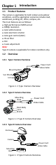
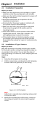
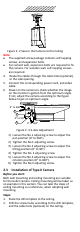
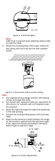
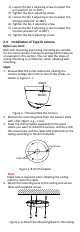
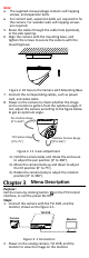
Table Of Contents

Note:
The supplied screw package contains self-tapping
screws, and expansion bolts.
For cement wall, expansion bolts are required to fix
the camera. For wooden wall, self-tapping screws
are required.
5. Route the cables through the cable hole (optional),
or the side opening.
6. Align the camera with the mounting base, and
tighten the screws to secure the camera with the
mounting base.
Figure 2. 10 Secure the Camera with Mounting Base
7. Connect the corresponding cables, such as power
cord, and video cable.
8. Power on the camera to check whether the image
on the monitor is gotten from the optimum angle. If
not, adjust the camera according to the figure below
to get an optimum angle.
Tilt Position Range
[0°to 75°]
Pan Position Range
[0° to 360°]
Rotation Position Range
[0°to 360°]
Figure 2. 11 3-axis Adjustment
1). Hold the camera body and rotate the enclosure
to adjust the pan position [0° to 360°].
2). Move the camera body up and down to adjust
the tilt position [0° to 75°].
3). Rotate the camera body to adjust the rotation
position [0° to 360°].
Menu Description
Purpose:
Call the menu by clicking button on the PTZ Control
interface, or call the preset No.95.
Steps:
1. Connect the camera with the TVI DVR, and the
monitor, shown as the figure 3-1.
Camera
TVI DVR
Monitor
Figure 3. 1 Connection
2. Power on the analog camera, TVI DVR, and the
monitor to view the image on the monitor.